Atmel ATtiny25 Stuff
 Just screwin' around.
I got a pile of ATtiny25's from Futurlec for various projects.
Resources and Credit
Atmel ATtiny25/45/85 product page
Adafruit Industries USBtinyISP AVR programmer & SPI interface
Adafruit Industries AVR Tutorial
AVR Libc Simple Project Demo
Files
AVR programming header symbols (gEDA PCB format): 6-pin, 10-pin
ATmel ATtiny25/45/85 part symbol (gEDA PCB format): here
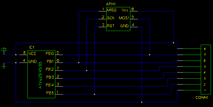
Target/Breakout Board schematic (gEDA gschem format): here
Target/Breakout Board
I needed a target board for programing, and I decided to make it a breakout board as well.
Marvel at my ten-minute schematic:
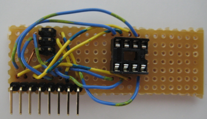
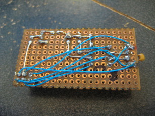
Stare in shock at my questionable wiring job:
Recoil in horror at my crappy soldering:
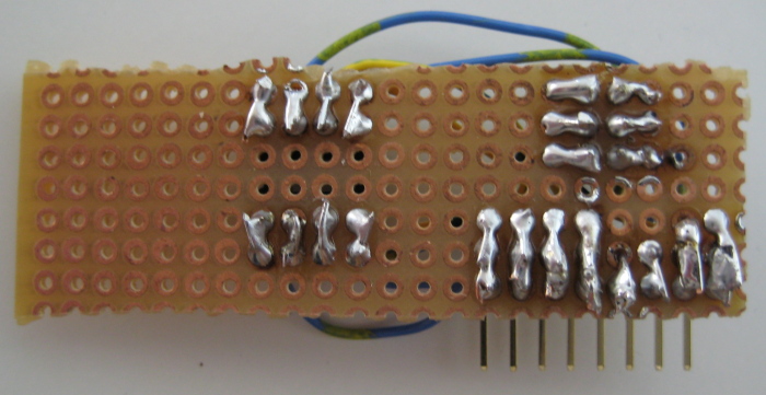
You can't tell from these photos, but I even managed to screw up the IC socket: one end is higher than the other!
I'm just hardcore like that.
And hot diggity! Wha'd'ya know? It works:
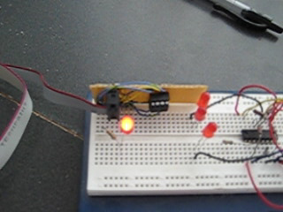
First try too. (Don't mind the stuff to the right on the breadboard - just me fiddling with an H-bridge.)
That IDC plug/ribbon cable is coming from my USBtinyISP AVR programmer. Turns out the five volts from my USB port is cleaner than my homemade bench supply.
While I'm here, mad props in general (to use the vernacular?) to Limor (who is way more engineer than I'll ever hope to be) - her site is crammed with tutorials and info, and she makes some useful kits to boot.
[2011-11-28]
So the board above was useful for a bit, but let me show you what I'm using these days:
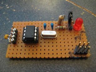
The new features are: an LED attached to pin 5 (PB0), and a 9,830,400Hz crystal (it divides nicely into 9600 and a few other serial baud rates) with supporting caps.
There is the usual programing header and a four pin connector for attaching daughter-boards or what-have-you (includes connections to PB1 and PB2 as well as power and ground).
So how does one get the crystal to work with an ATiny25? I'm glad you asked.
Figure 6-5 on Page 30 of the datasheet outlines the hardware:
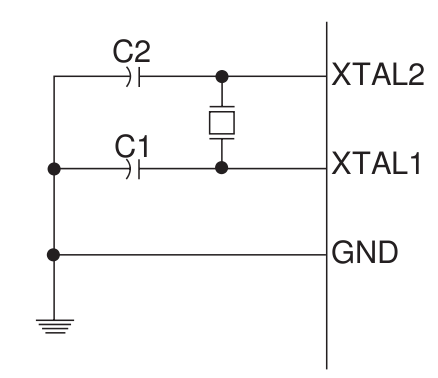
The values of C1 and C2 are usually dictated by the crystal manufacturer.
Now we still need to set the appropriate 'fuses' (see Page 152) on the chip so that it knows to use the crystal and not the internal 8MHz RC oscillator.
This particular chip has three fuse bytes: high, low, and extended. We can read the fuse bytes with the following commands (on Ubuntu 10.04 at least):
	sudo avrdude -c usbtiny -p t25 -U lfuse:r:-:b
	sudo avrdude -c usbtiny -p t25 -U hfuse:r:-:b
	sudo avrdude -c usbtiny -p t25 -U efuse:r:-:b
The clock source settings are in the low fuse byte.
Here is a copy of the table on Page 153 on the datasheet, reproduced with no permission whatsoever:
| Fuse Low Byte |
Bit No |
Description |
Default Value |
| CKDIV8 |
7 |
Clock divided by 8 |
0 (programmed) |
| CKOUT |
6 |
Clock output enabled |
1 (unprogrammed) |
| SUT1 |
5 |
Start-up time setting |
1 (unprogrammed) |
| SUT0 |
4 |
Start-up time setting |
0 (programmed) |
| CKSEL3 |
3 |
Clock source setting |
0 (programmed) |
| CKSEL2 |
2 |
Clock source setting |
0 (programmed) |
| CKSEL1 |
1 |
Clock source setting |
1 (unprogrammed) |
| CKSEL0 |
0 |
Clock source setting |
0 (programmed) |
We want to turn off the 'divide clock by 8' function, and select the external crystal. Take a look at Table 6-11 on Page 30 for the correct value to use to enable the crystal:
| CKSEL3:1 |
Frequency Range (MHz) |
| 100 |
0.4 - 0.9 |
| 101 |
0.9 - 3.0 |
| 110 |
3.0 - 8.0 |
| 111 |
8.0 - |
We're running at ~9MHz so we want to set CKSEL3:1 to '111'. Note the range; CKSEL0 appears to be related to 'ATiny15 compatability mode'.
In this example the final fuse setting should be this: 0b11101110 or 0xEE.
To write this setting, we run this command:
sudo avrdude -c usbtiny -p t25 -U lfuse:w:0xEE:m
And we're done.
DISCLAIMER
All content is owned by its respective creators/licence holders.
Unless otherwise stated, everything else: Copyright © 2009, Chlazza

