M12 Light Reconnaissance Vehicle, Electric Conversion (EV Warthog)
 I don't really celebrate Christmas in the religious sense - I just like getting free stuff. Plus my mom makes a bunch of pies, but I digress.
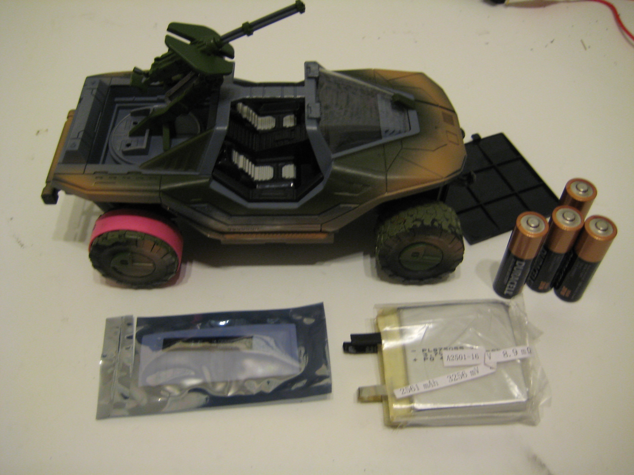
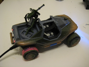
To nobodies surprise (probably) I happen to thoroughly enjoy the Halo series of video games. As such, a friend of mine got me a franchise tie-in product as a Christmas gift - an R/C Warthog toy. It's clearly made by the lowest bidder (the case doesn't quite fit together right, the wheels aren't even rubber) but works well enough to chase the cats around. Annoyingly it didn't ship with the 6 (!) double-A cells needed to run. We managed to scrounge up some cells from the all the TV remotes and various tools in the house, but they were all at different depths of discharge and the 'hog was sluggish at best. Clearly, I thought to myself as I watched the anemic vehicle slowly roll toward the family cat, There Must Be A Better Way™. Coincidentally, I recently ran across a rather well stocked web-based battery supplier (they were mentioned by John Carmack) who stocks (among other things) 'raw' Lithium Ion and Lithium Polymer cells.
I bet you can see where this is going.
Resources and Credit
Batteryspace.com - West-Coast based distributor for a consortium of China-based battery manufacturers.
The Warthog
To be fair, this project wasn't entirely my idea. The 'hog came with a extra requirement from the gifter: it must be hacked. Additionally, if I managed to inadvertently wreck it, another one would be supplied.
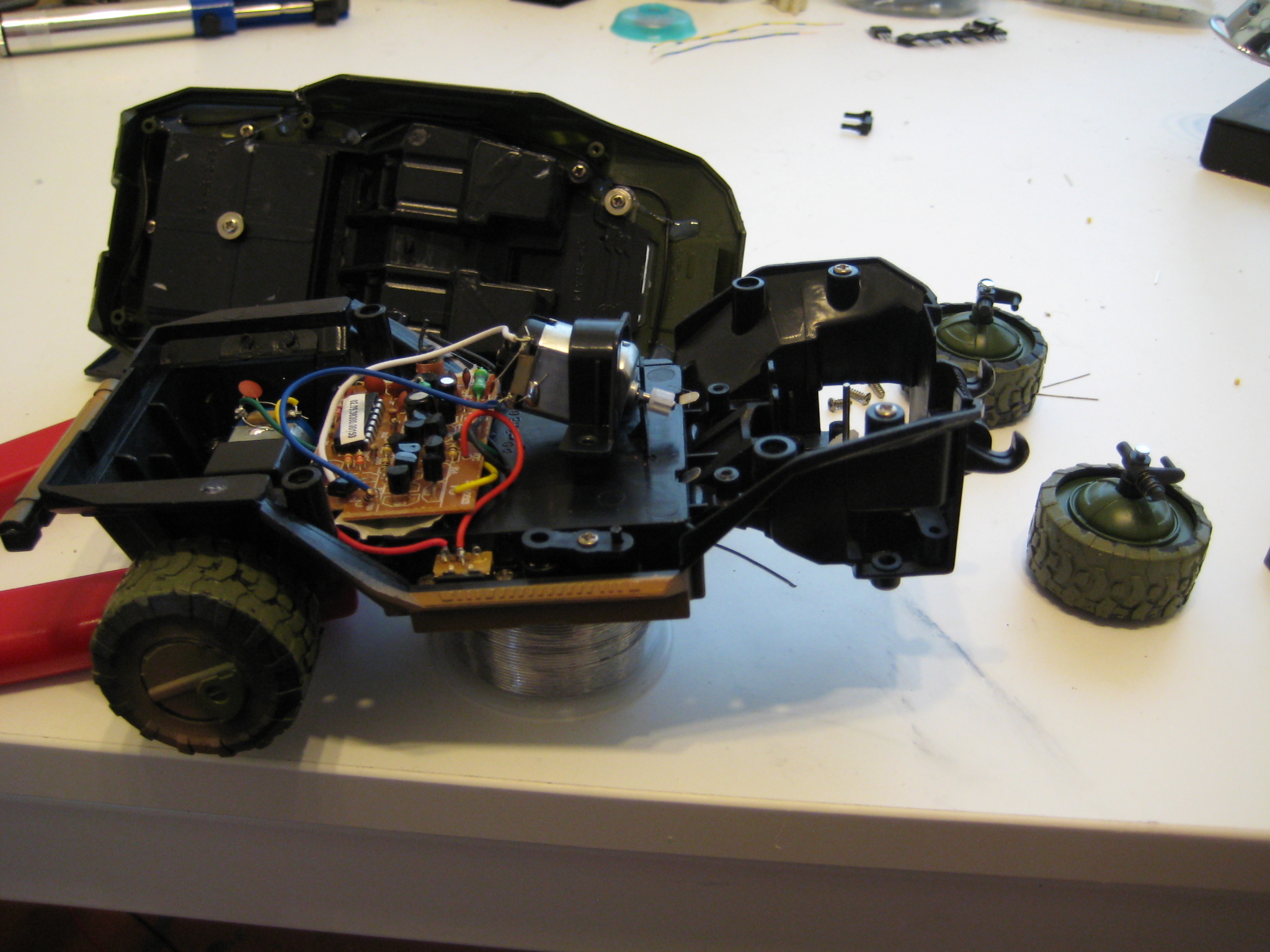
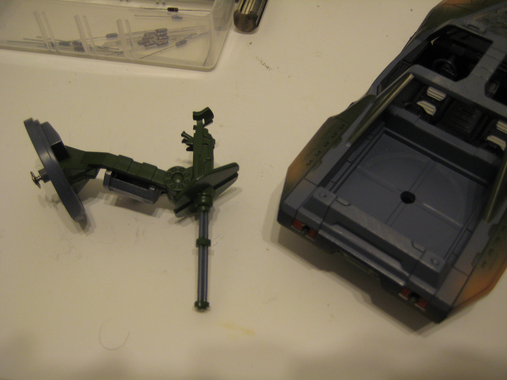
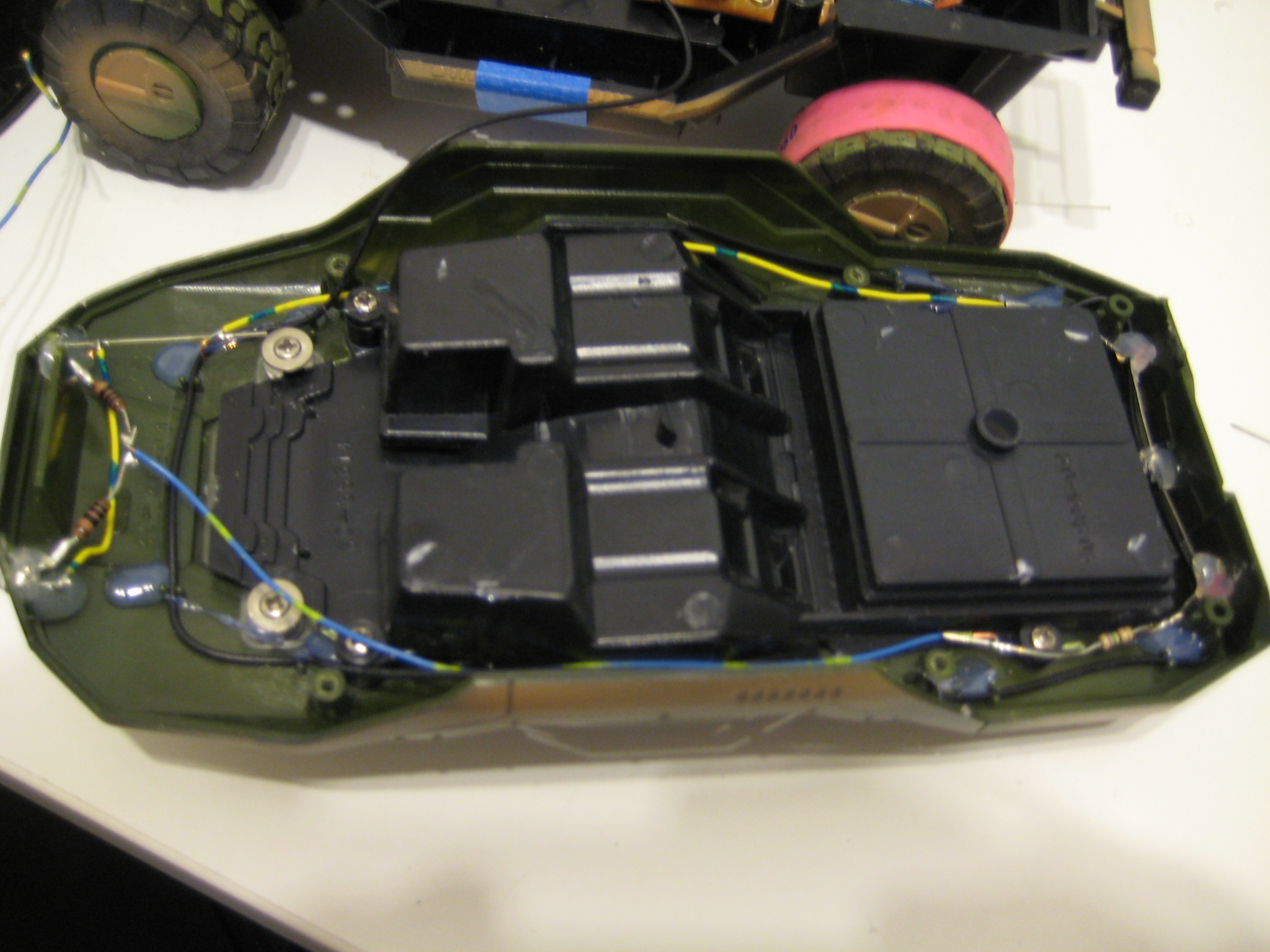
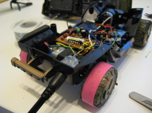
With the worry of wrecking a perfectly good new toy removed from the picture, I dismantled the damn thing as soon as I got home:
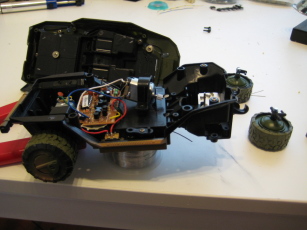
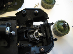
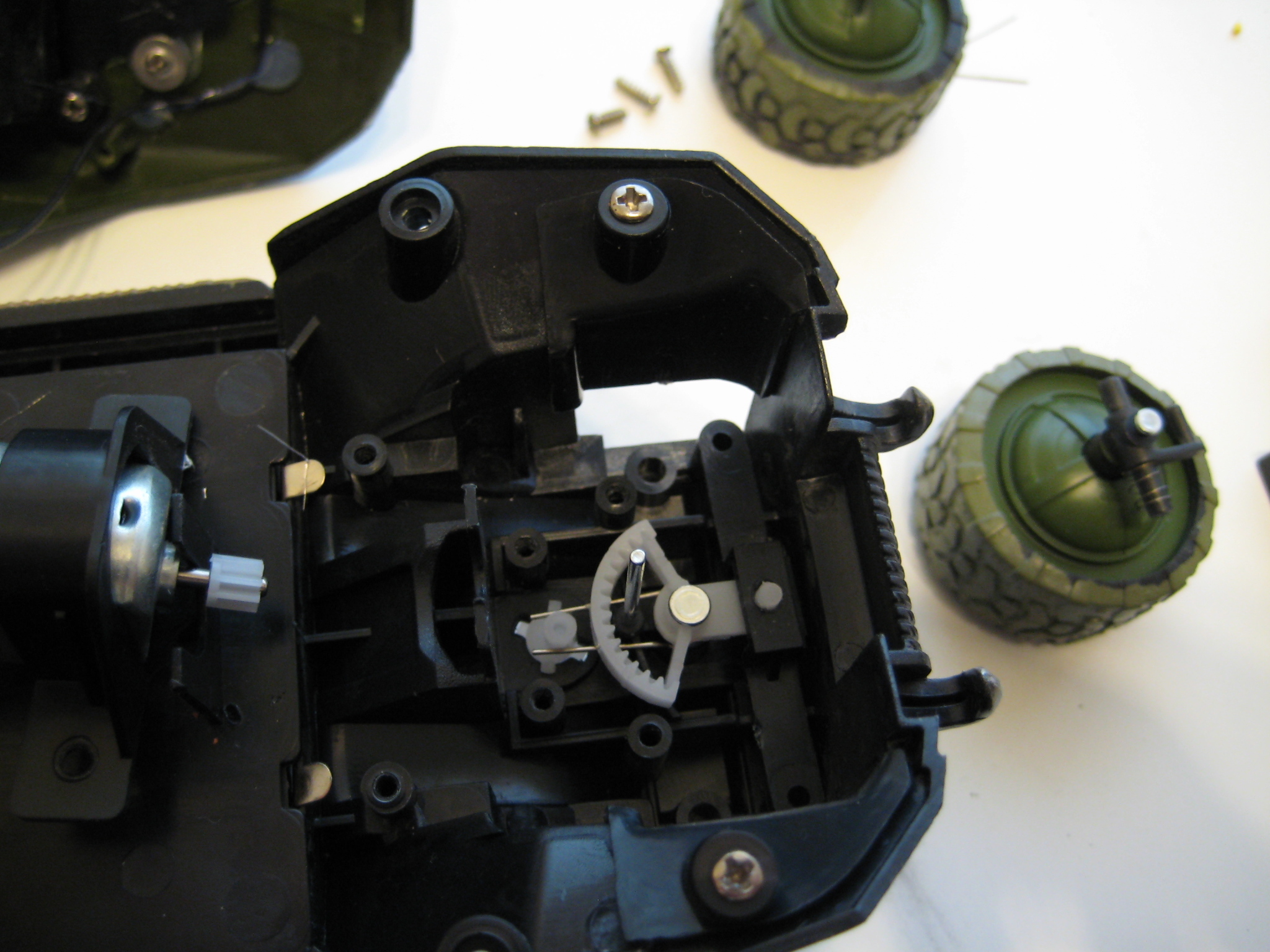
The design was pretty straight forward. One DC motor in the back drives two fixed wheels, and one motor in the front is used to slue the front wheels left or right. The gearing in the back isn't what I would choose - it's low on torque and high in speed. It takes a few seconds to get going, but once it does it's off like a rocket. I want to replace all the electronics at some point in the future - put a better motor in the back and put in a servo instead of motor driven to stall. We'll see though.
The wheels have really crappy traction to the point where wheelspin would occur every time the 'hog was driven on anything except carpet. The 'tires' feel like hard plastic, which makes them pretty bad when it comes to driving on things like tile. A friend of mine suggested that I put some rubber bands on the wheels - a bit of rummaging later and we found a couple (came on broccoli I think) that fit perfectly. It still does the occasional burnout and the rear wheels drift with no help, but as the same friend pointed out, it wouldn't be a Warthog if it didn't.
Battery Selection
I wanted to replace the batteries with something rechargeable (for obvious reasons) and something that match or exceeded the capacity of standard AA's. The best disposable AA's that I could find were rated 1.5Ah with a nominal voltage of 1.5V - four in the 'hog in series brought the nominal voltage to 6V. I didn't even bother looking at lead-acid cells, for obvious reasons. NiCad cells couldn't match the power density. NiMH cell have respectable power density but have high-self discharge rates, are difficult to charge correctly, and buying some NiMH double-A's and an external charger isn't really a hack. The Lithium Ion chemistry is notorious for high power density, simple charge requirements, and exploding in ones face.
The most ballin' shit in batt tech today is the Lithium Iron Phosphate (LiFePO4) cell chemistry - supposedly much less volatile than the traditional Lithium Ion (LiCoO2/LiMnxNiyCozO2) chemistry, a cycle life to rival that of NiCads, and a power density better than NiMH. When I first evaluated this option, I was surprised to note that the LiFePO4 AA's I sourced actually had a power density that was worse than the AA NiCads I had found: 0.6Ah versus 1Ah respectively. At that point I cast my eyes warily back to Lithium Ion. In retrospect I realized I had made a rather boneheaded mistake: I forgot to take in account the difference in cell voltages. Comparing watt hours per unit mass gives numbers more in line with expectations. Assuming a 'mass' of four double-A's: LiFePO4 comes in at 3.2V * 0.6Ah * 4 = 7.68Wh. NiCads clock in at 1.2V * 1Ah * 4 = 4.8Wh. However, compare these to the best disposable AA's I could find: 1.5V * 1.5Ah * 4 = 9Wh. Granted, the voltage noted is probably wishful thinking - I'm willing to bet that it's more in line with NiCad cells (particularly at the end of its discharge curve), but that still results in 7.2Wh which is barely edged out by LiFePO4 cells.
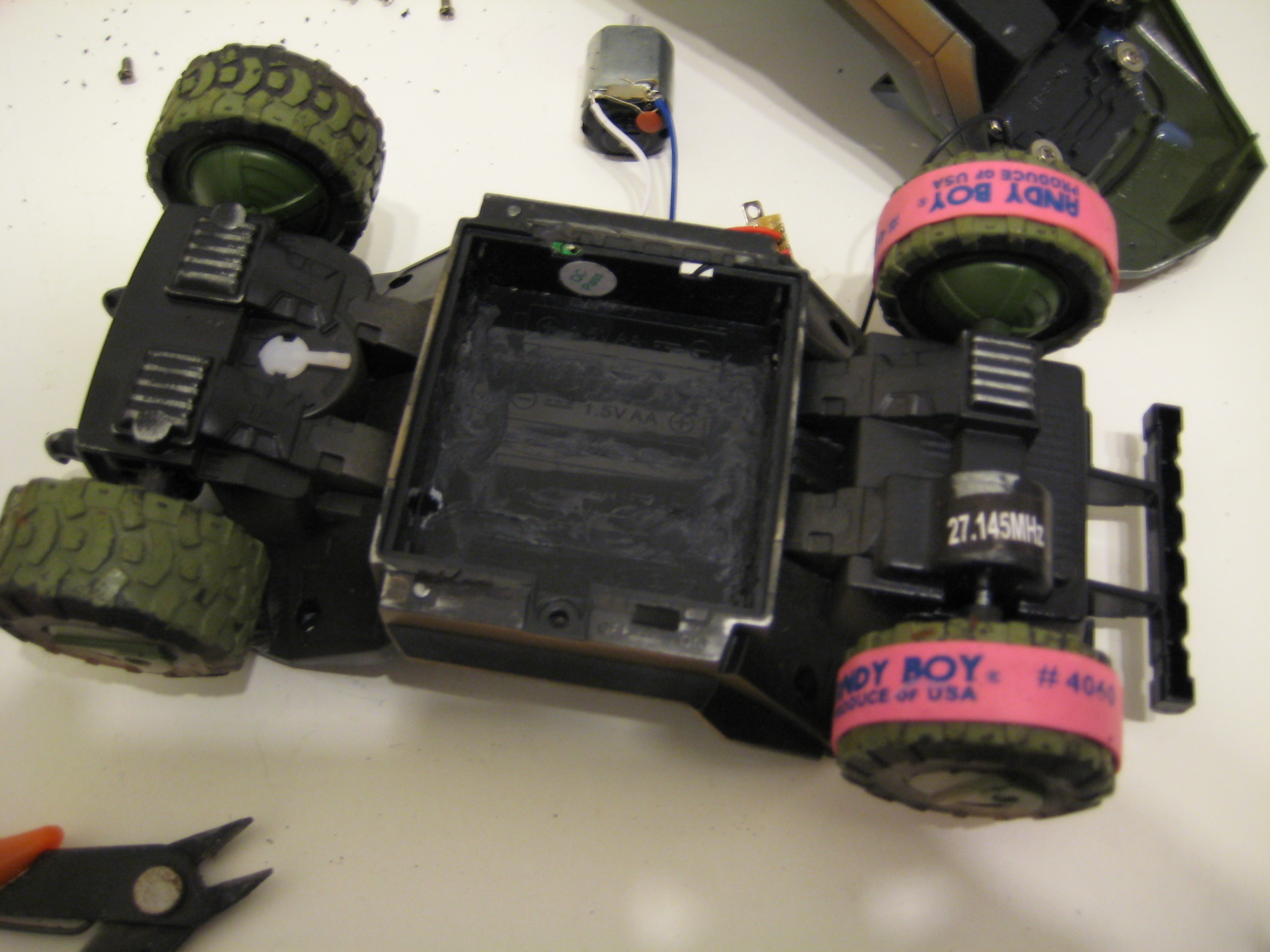
One thing about cylindrical cells: they're not really space efficient. No matter how you pack them there is going to be some gaps. At this point I figured that I was going to be going with something from the Lithium family (given the power density issue), and one of the nice things about the Lithium chemistry is that they are available in a variety of pouch/prismic form factors. I'd need to carve out the molded-in AA battery holder in the underside of the Warthog, but that didn't look impossible. Sadly, Battery Space didn't have any pouch/prismic cells in the LiFePO4 chemistry that would fit in the warthog battery compartment. They did, however, have a wide assortment of pouch-style cells in the more common (more explody) Lithium Ion chemistry.
As per my modus operandi, I put concerns about my well-being in the basement and slid the gunsafe over the trapdoor.
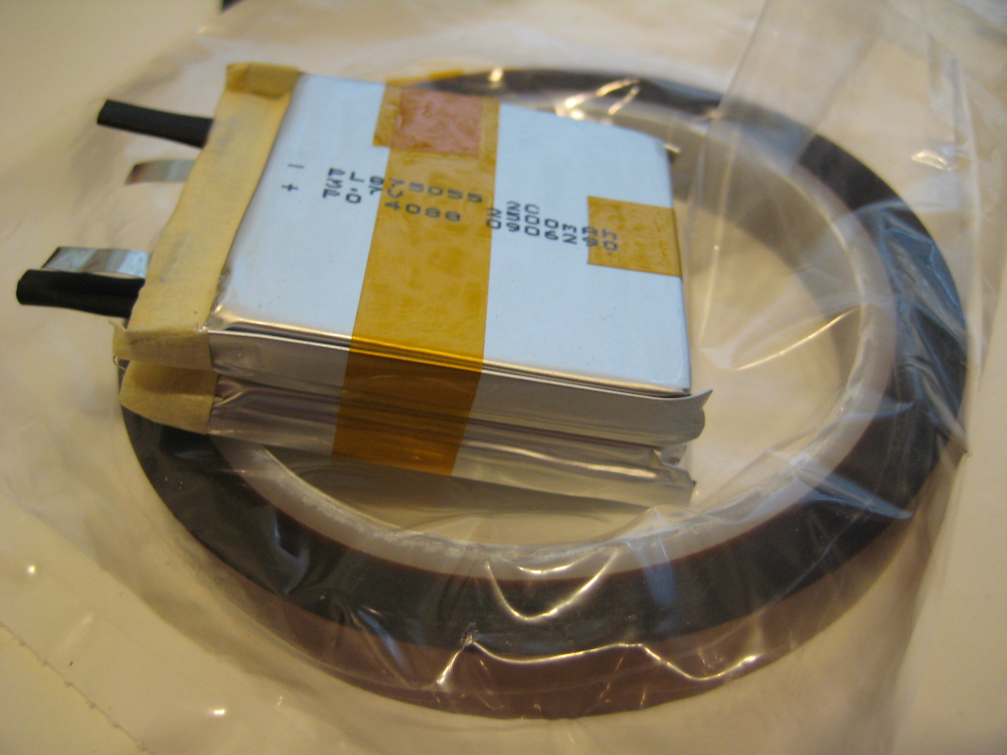
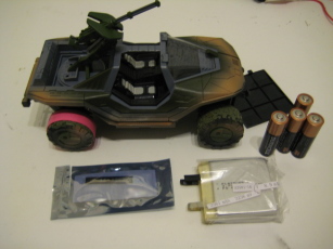
Rounding down to the nearest divisible-by-five number, the battery compartment of the 'hog (sans double-A holders) measures roughly 55mm long by 60mm wide by 15mm deep. I found these suckers that clock in at 55mm long by 50mm wide by 8.7mm thick - a near perfect fit. Each cell has a capacity of 2.5Ah, although I'd need two cells to get the voltage I needed which technically blows my depth requirement, but not by much. The capacity for this pack works out to be 3.7V * 2.5Ah * 2 = 18.5Wh - slightly more than twice the pack of disposable double-A's! Now these are 'raw' cells, meaning they don't have the over-voltage/under-voltage protection circuit that all consumer-available Lithium Ion cells (cell phone and laptop batteries) come with. I didn't exactly have a wide selection, and I went with this one. In the interest of reliability I also picked up an appropriate charger.
Parts
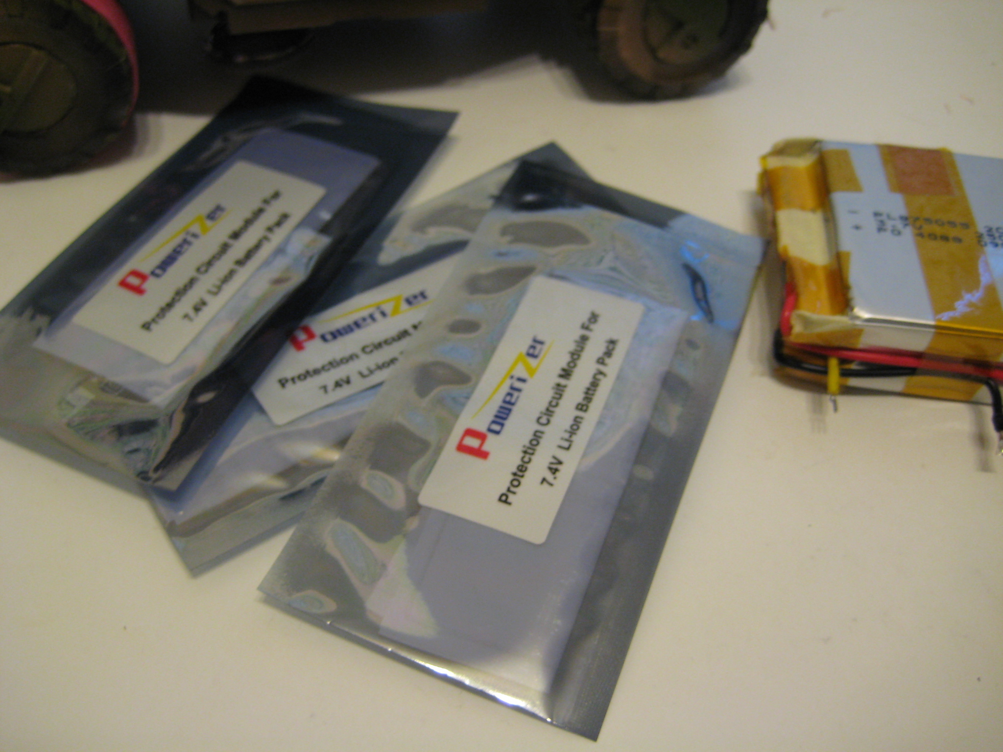
PL-875055-2C - 3.7V 2.5Ah Lithium Polymer cells (datasheet, local copy)
PCB-S2A5 - 7.4V (two cell) LiIon/LiPoly battery pack overvoltage/undervoltage/overamp protection circuit.
CH-UNLI7405 - 8.4VDC@0.5A LiIon/LiPoly charger.
Generic 7805 - 5VDC@1A regulator, TO-220 package. I think it was from Fairchild Semiconductor?
[2010-01-16]
Cells and related parts arrived about a week ago. Also bought some Kapton tape from McMaster-Carr.
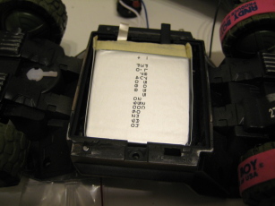
Finally got time to borrow a Dremel rotary tool from a friend to grind out the AA battery case. I scarred up the case pretty badly, but didn't poke through anywhere - not bad for a first try. I'm still pulling plastic bits out of my hair though.

The irony of this project is the price. The Warthog? ~25USD. All the battery parts? ~60USD. Yeeeeah.
[2010-01-17]
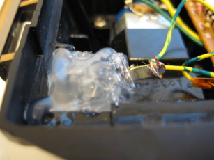
I love me some Space Tape.

It's polyimide film with a silicon adhesive - usually found being sold under the 3M brand name 'Kapton'. It is a great electrical insulator, has a huge temperature range, doesn't expand or contract much with temperature change, and resists most chemicals. This is my favorite tape.
Yes, I have a favorite tape. Shut up.
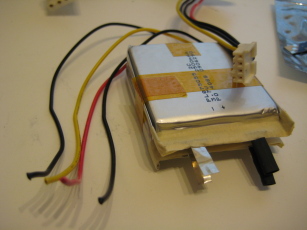
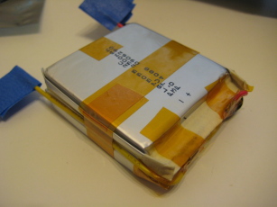
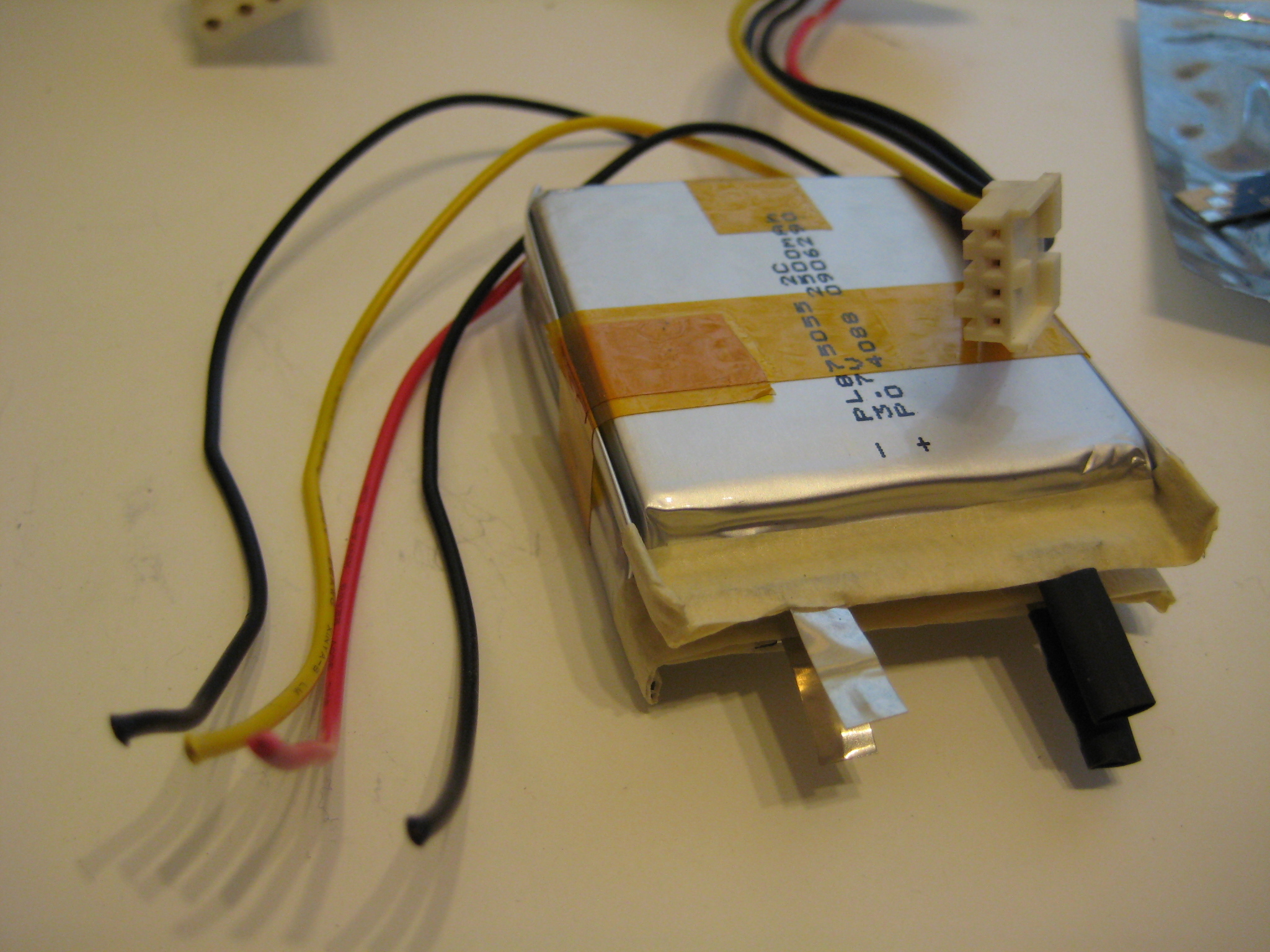
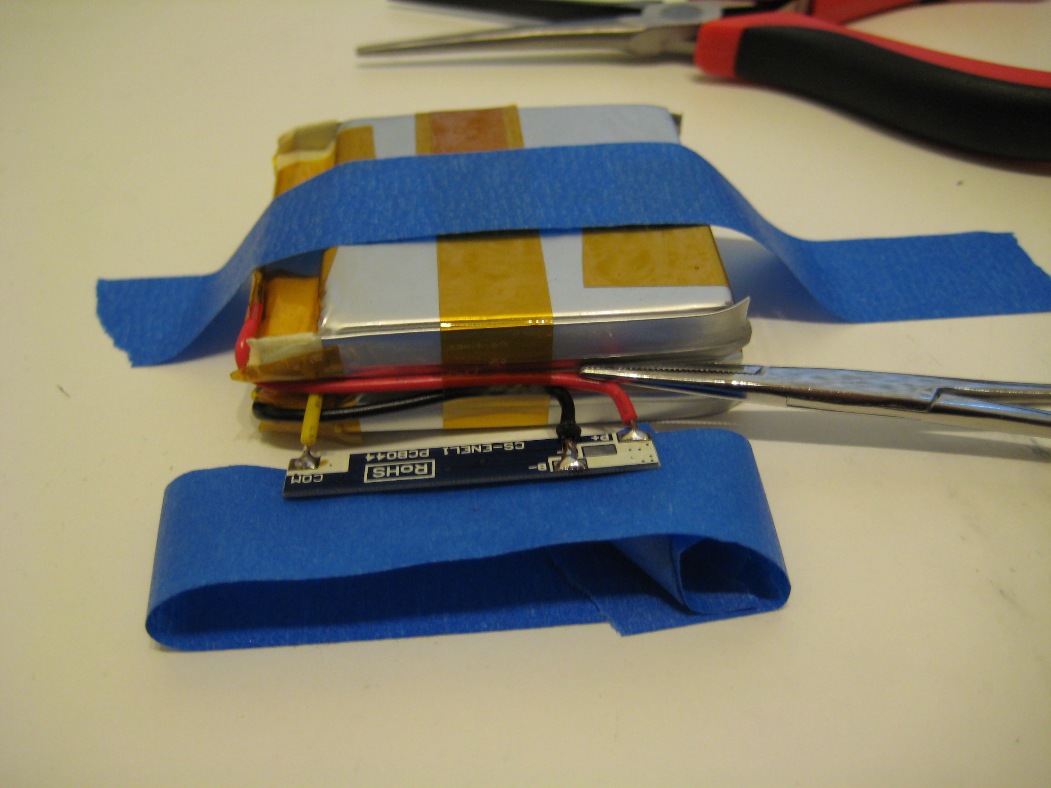
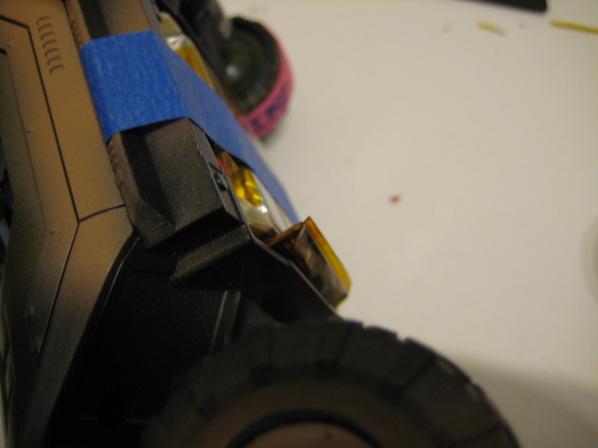
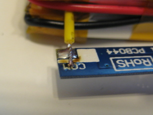
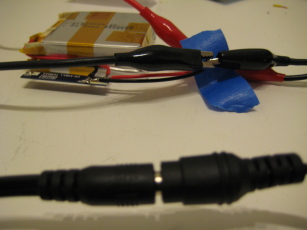
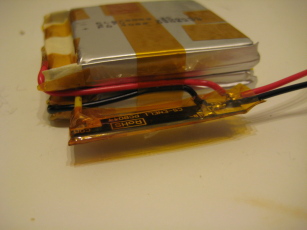
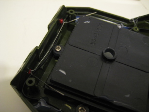
I salvaged some 20AWG wire from a floppy disk drive power connector cable I pulled off a non-functional ATX power supply. The two cells were attached in series, and I just bent the tabs over the stripped ends of the wire and 'crimped' it closed with a pair of hemostats and long nose pliers. I doused them with solder just to make sure everything stayed put and then taped them up. The blue painters tape is a temporary measure to keep the ends of the wires from touching and shorting out the pack.
As you can probably tell, the common connection (yellow wire) was my first connection completed.
A quick test fit. The pack fits perfectly, except there is no space at the ends - I realized I would need to put the protection module along one of the sides of the pack if I was going to fit it all in that space.


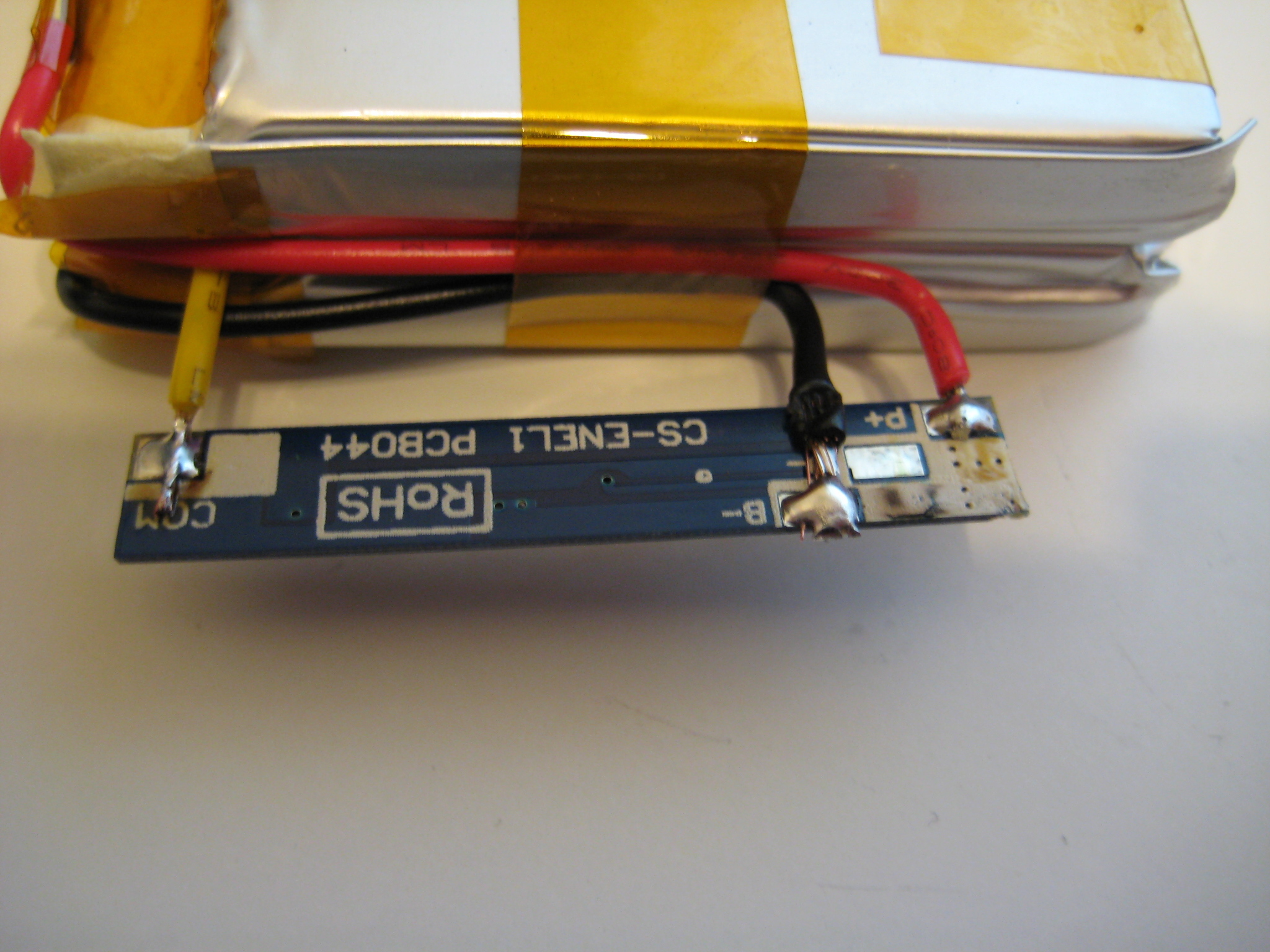
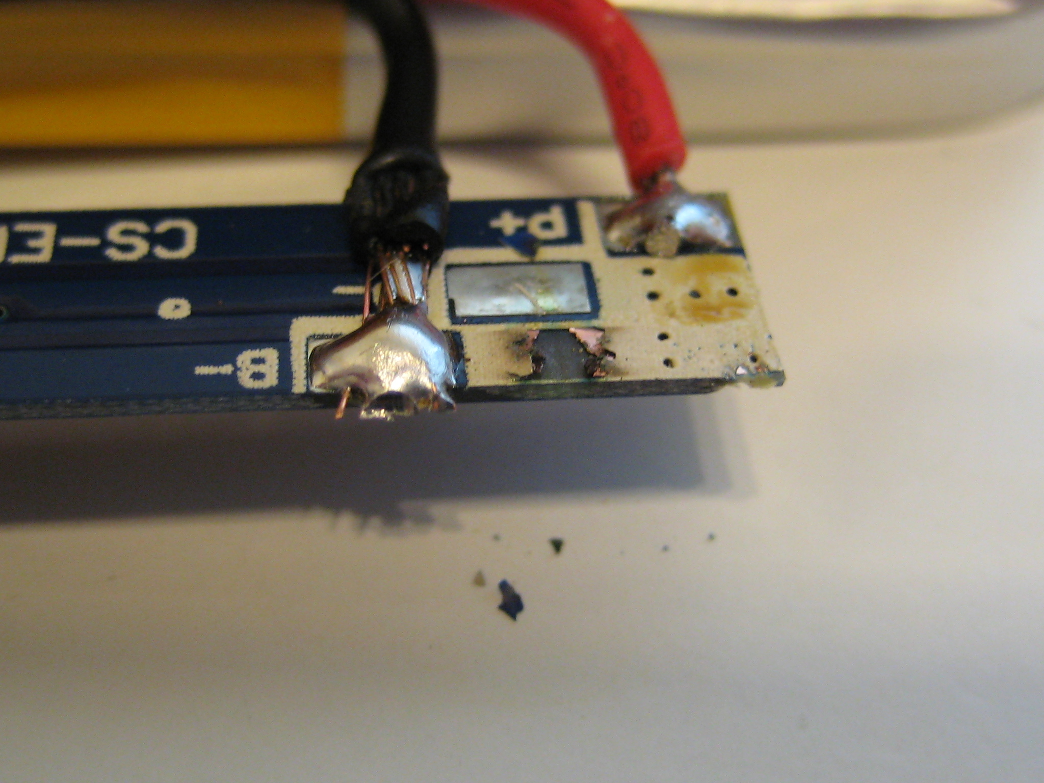
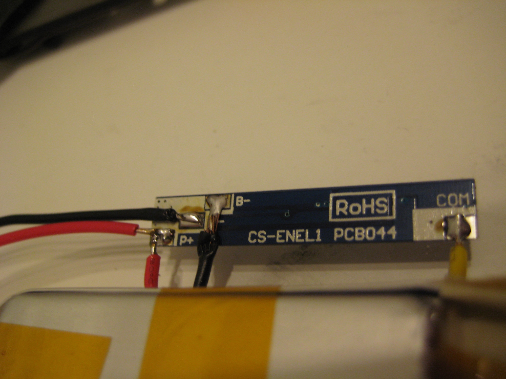
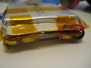
I don't have one of those 'third-hand' thingys, so I was using painter tape to hold everything in place while I soldered the joints. Right around the time when I was soldering on the last wire (the red one) I accidentally scraped up the silkscreen/solder mask on the board and shorted something out.
Whoops.
The cells seem fine, but the board itself is giving out zero volts now. It looks like I could just dab some solder across that burned trace in the last picture - however in the interest of safety I decided to not risk it. I'm gonna need to buy another module.
[2010-01-22]
Okay then. Take 2 - now with less suck.

Bought a couple of extras this time.


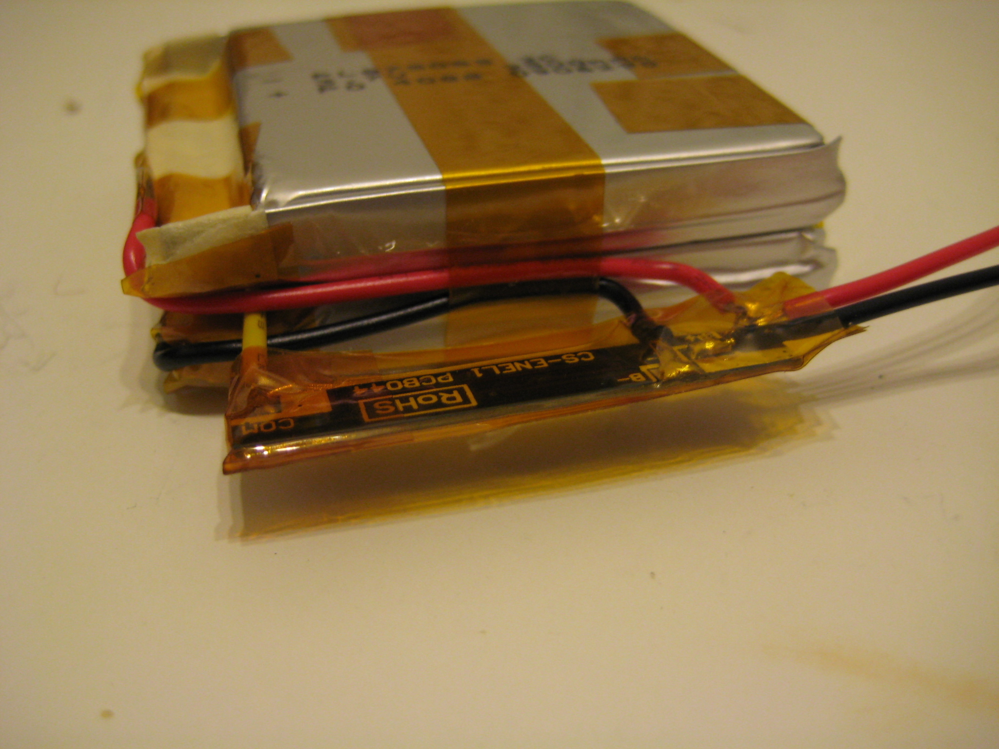
Using a loop of masking tape as a sort of pad/spring proved to be a very effective way of holding the protection circuit at a useful level.
Here's one 'gotchya' that stumped me for a few days.
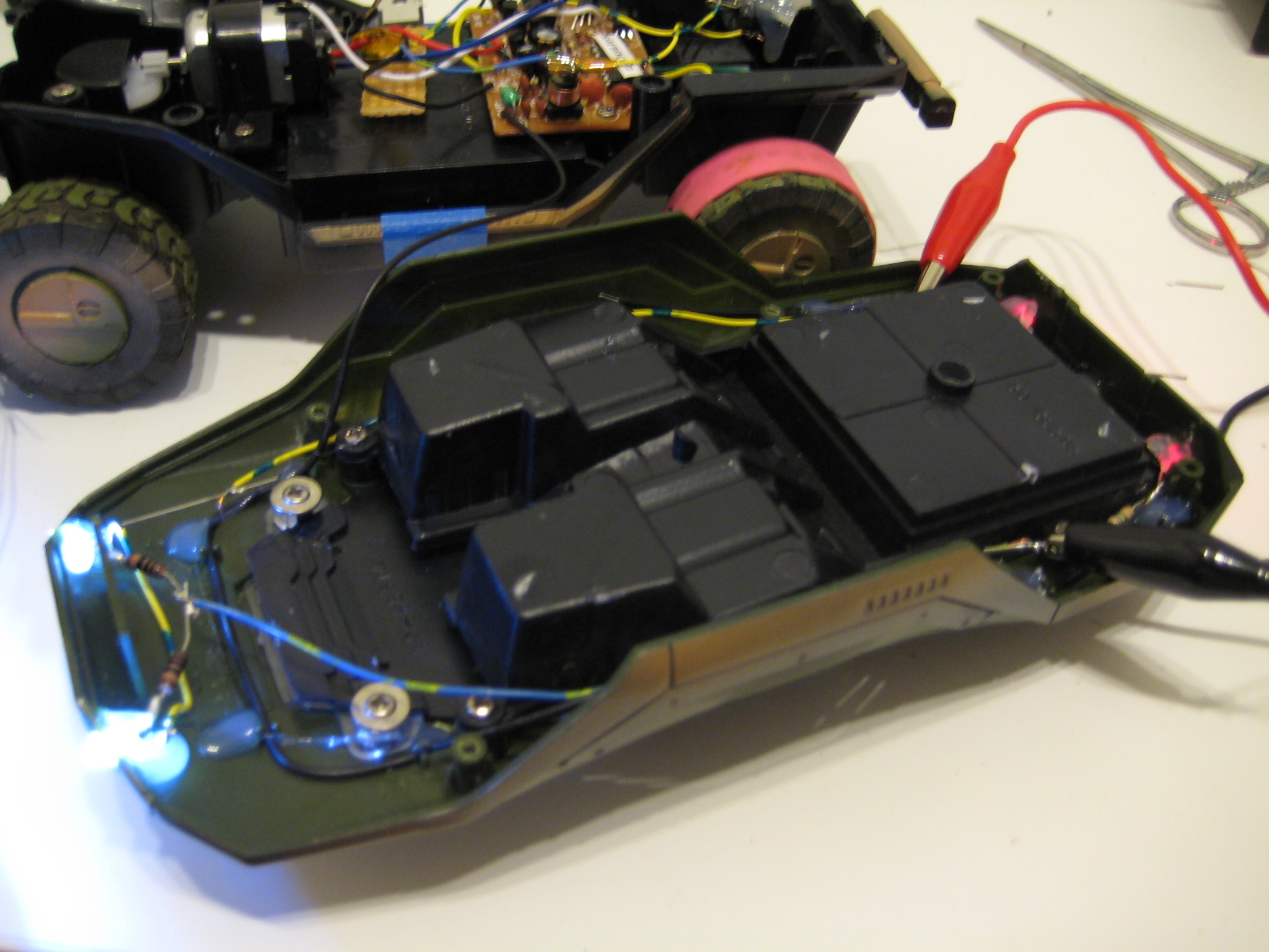
After attaching the board, I couldn't get any voltage out of it. The cells were outputting voltage above the cut-off limit of the circuit, but the circuit outputs were at zero volts. It sat on my desk for a couple of days while I was distracted by other things, until last night when I decided to attach it to the charger and see if that lit anything up. These circuits are supposed to be autoresetting, and I was under the impression they reset when the battery voltage was appropriate - but maybe something was floating and confusing it, or maybe it was quirk with this chip. I attached the charger, and then unplugged it a moment later. When I looked up my multimeter was reading about 7.6V across the output lines of the pack. w00t.

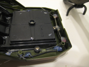
In the end the protection circuit sticks out of the bottom of the battery case. Oh well. Need to work on my precision wire-stripping next time.
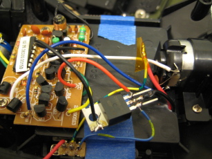

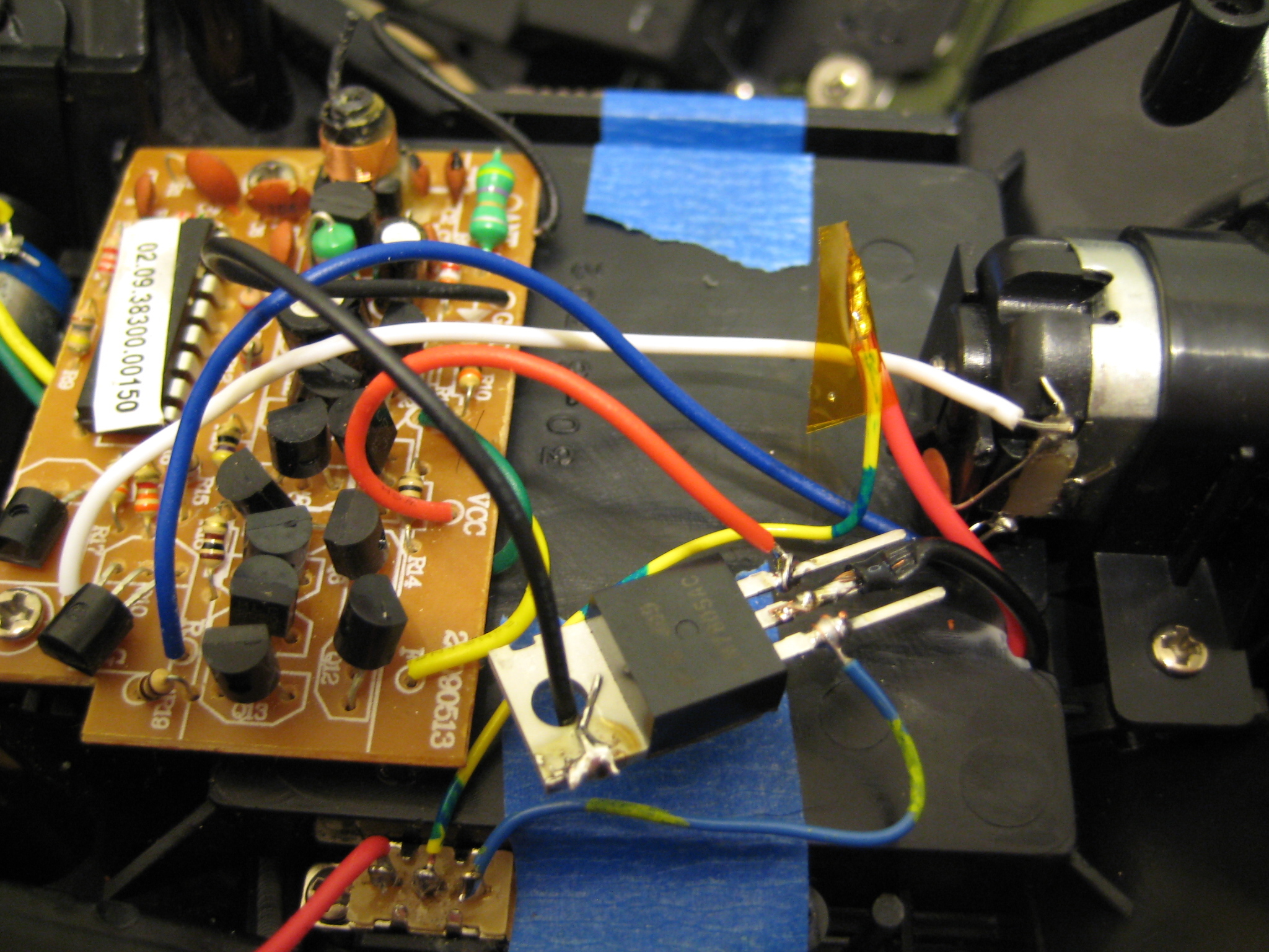
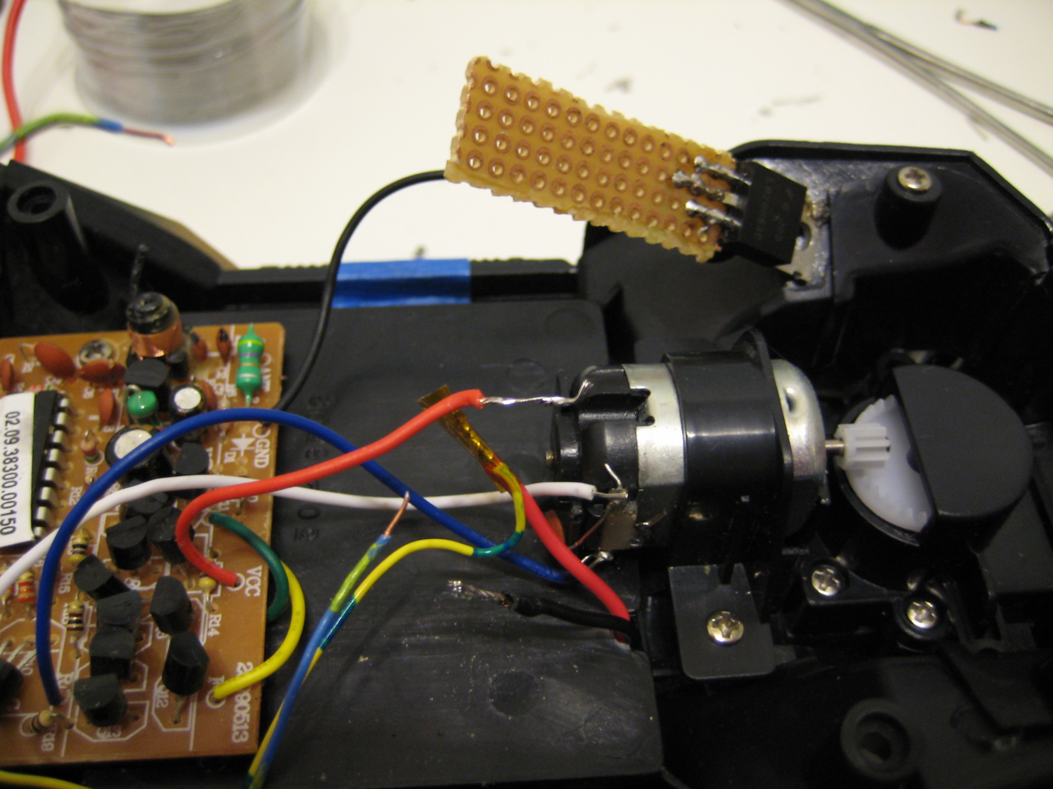
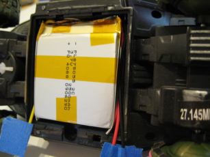
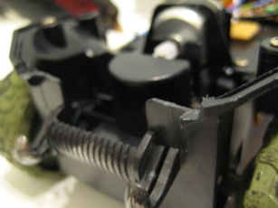
The warthog electronics were designed to run off of 4 double-A's, which works out to be about 6 volts (assuming peak voltage off each cell). When fully charged the new pack would deliver upwards of 8 volts. I was temped to just wire them in, but decided against the chance of totally blowing everything. Instead I wired in a 5V regulator, assuming that it would simulate the power of not-quite-perfectly-fresh pack of disposable double-A's.
Note the switch in the lower left. That's the original power switch - turns out its a Single-Pole-Dual-Throw. I wired the battery to the common connection, and attached the internal electronics to the free connection (on the right in the picture). This has the odd effect of having the Warthog powered up when the switch is in the 'off' position, but simplifies the wiring: the extra red wire on the left of the switch will eventually connect to a power jack in the back of the 'hog that will accept the connector on the end of the charger I picked up.
And the Warthog runs great! I haven't tried to drain the pack yet, but it has speed - it looks like 5V was a good value to use.
Things to do: Charger socket (2.1mm ID circular power jack).
Things I want to do: Add head and tail lights. Completely redo electronics. Servo on the front steering (preq is new electronics).
[2010-01-23]
Charging socket done!
Sadly, when I went to put the top back on, the antenna wire snapped off the PCB.
*sigh*
It still works, but you need to have the controler antenna about 6cm away from the 'hog. Not exactly useful. I'll probably fix that next weekend.
[2010-01-29]
So the parts arrived earlier than I expected, and I couldn't wait until this weekend.


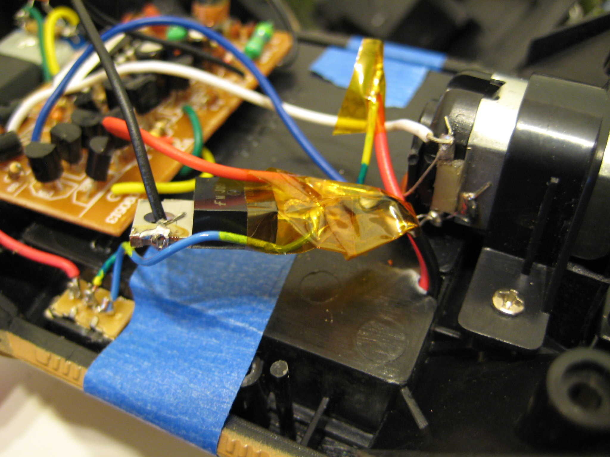
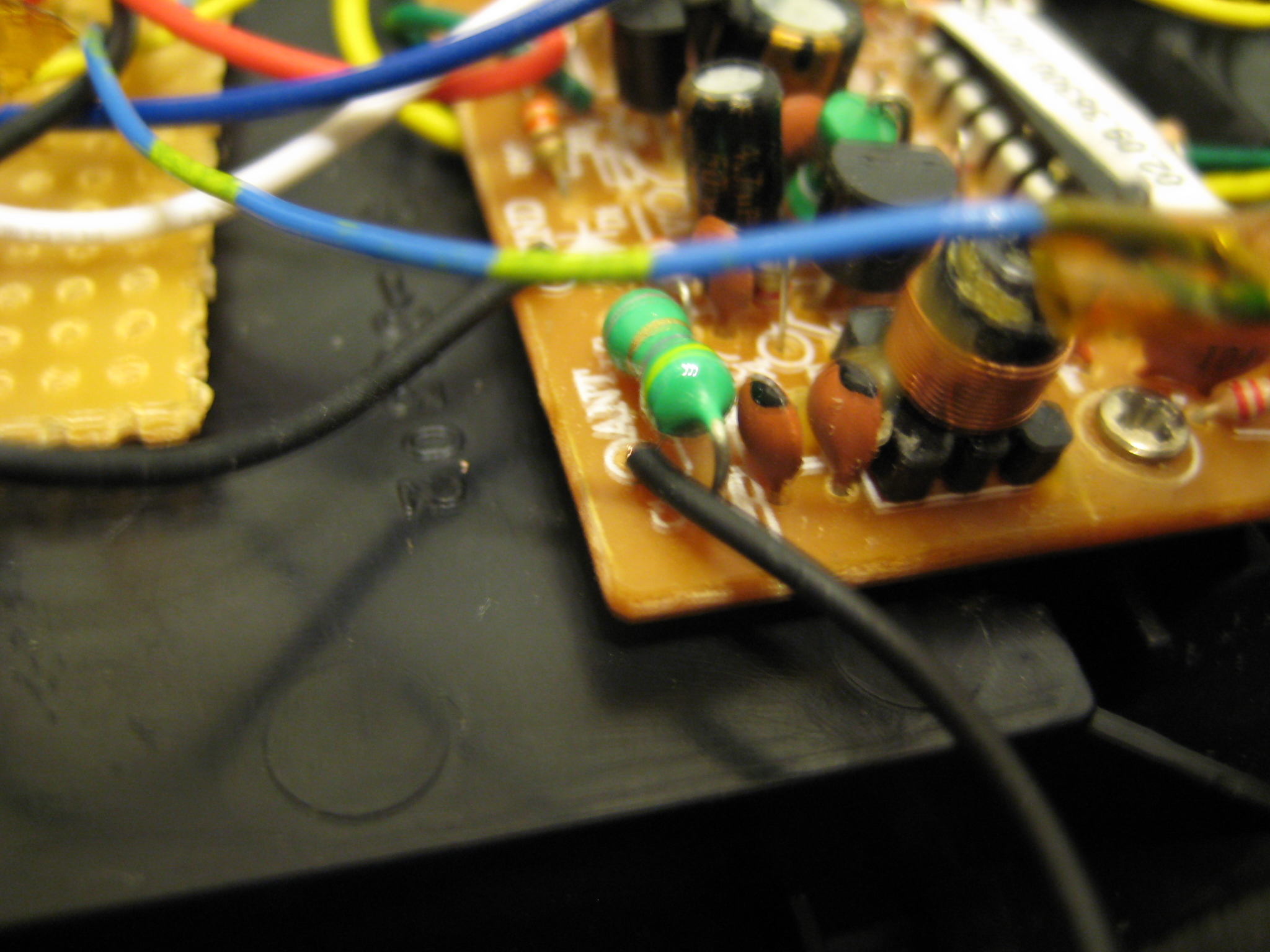
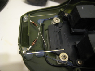
I redid the power distribution - previously it was just the 7805 linreg with bits of wire wrapped around its pins. This time I used a scrap of perf board to mount the regulator and poked wires though holes - almost looks professional.
I also reattached the antenna wire - for some reason, the original construction had the wire soldered to the bottom of the board, rather than use the perfectly good drilled and tinned hole in the board.
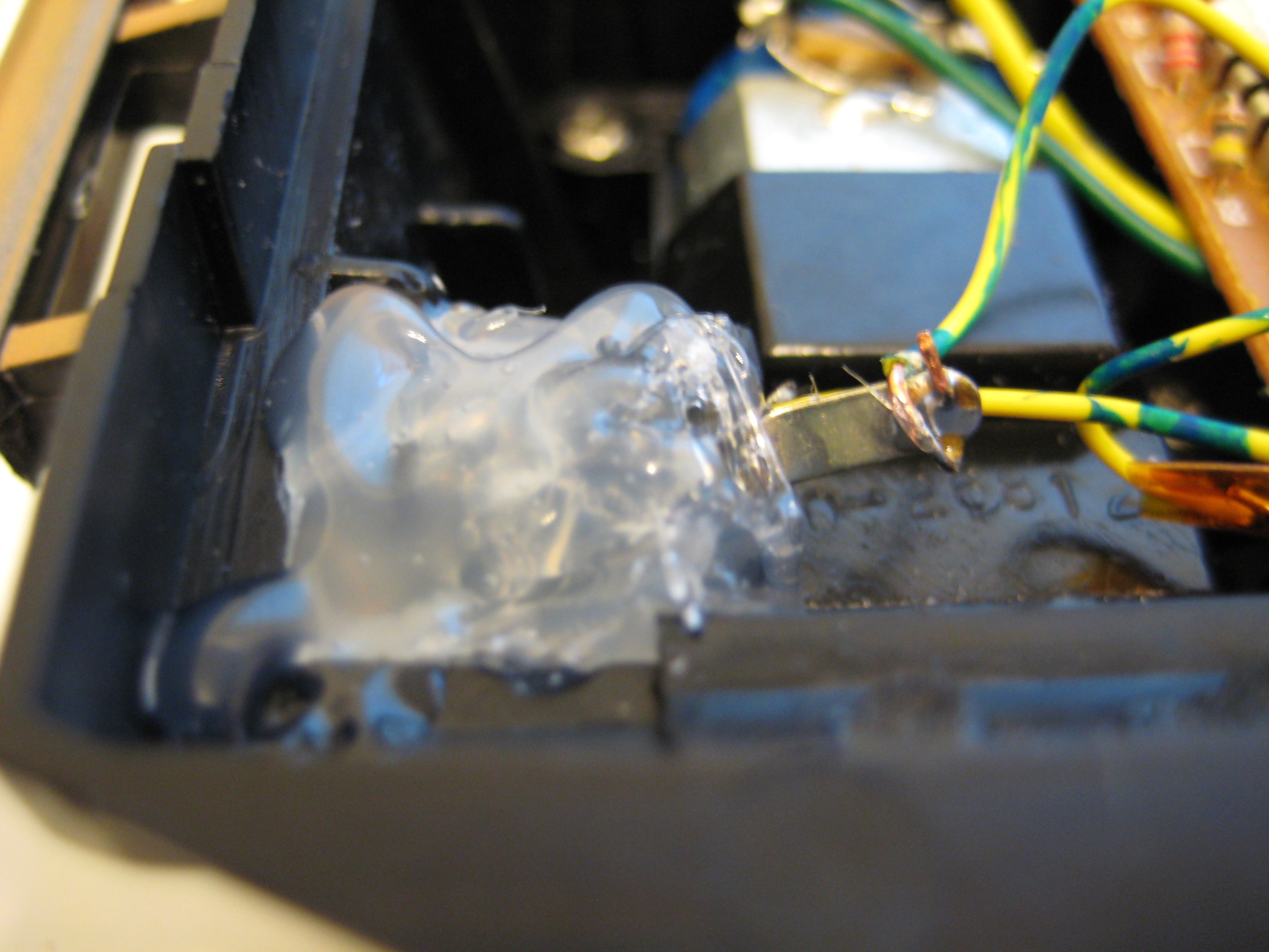
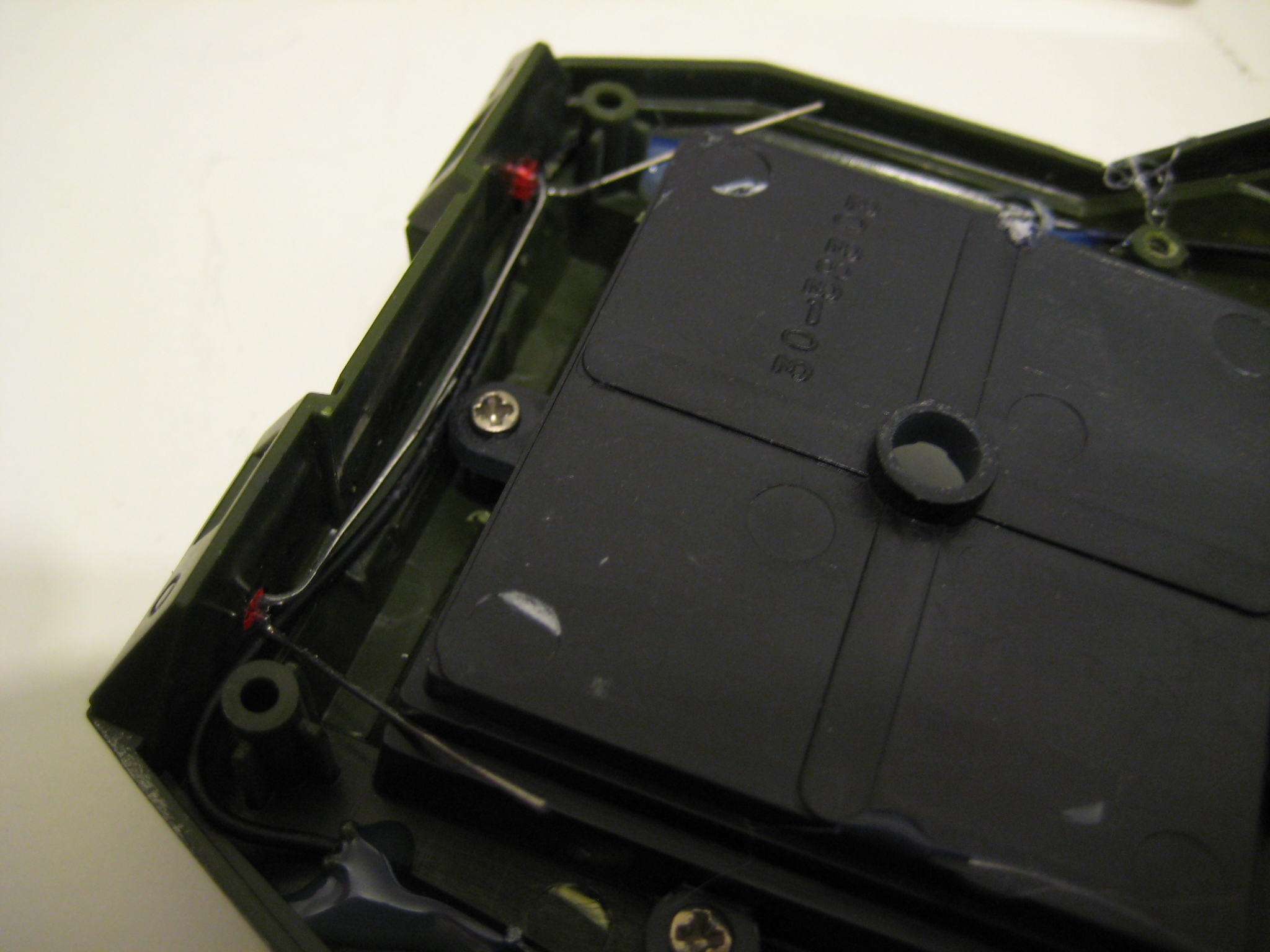
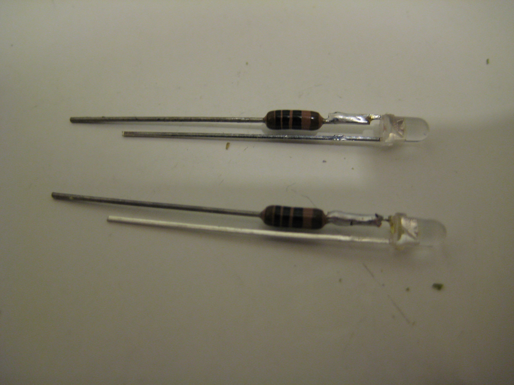
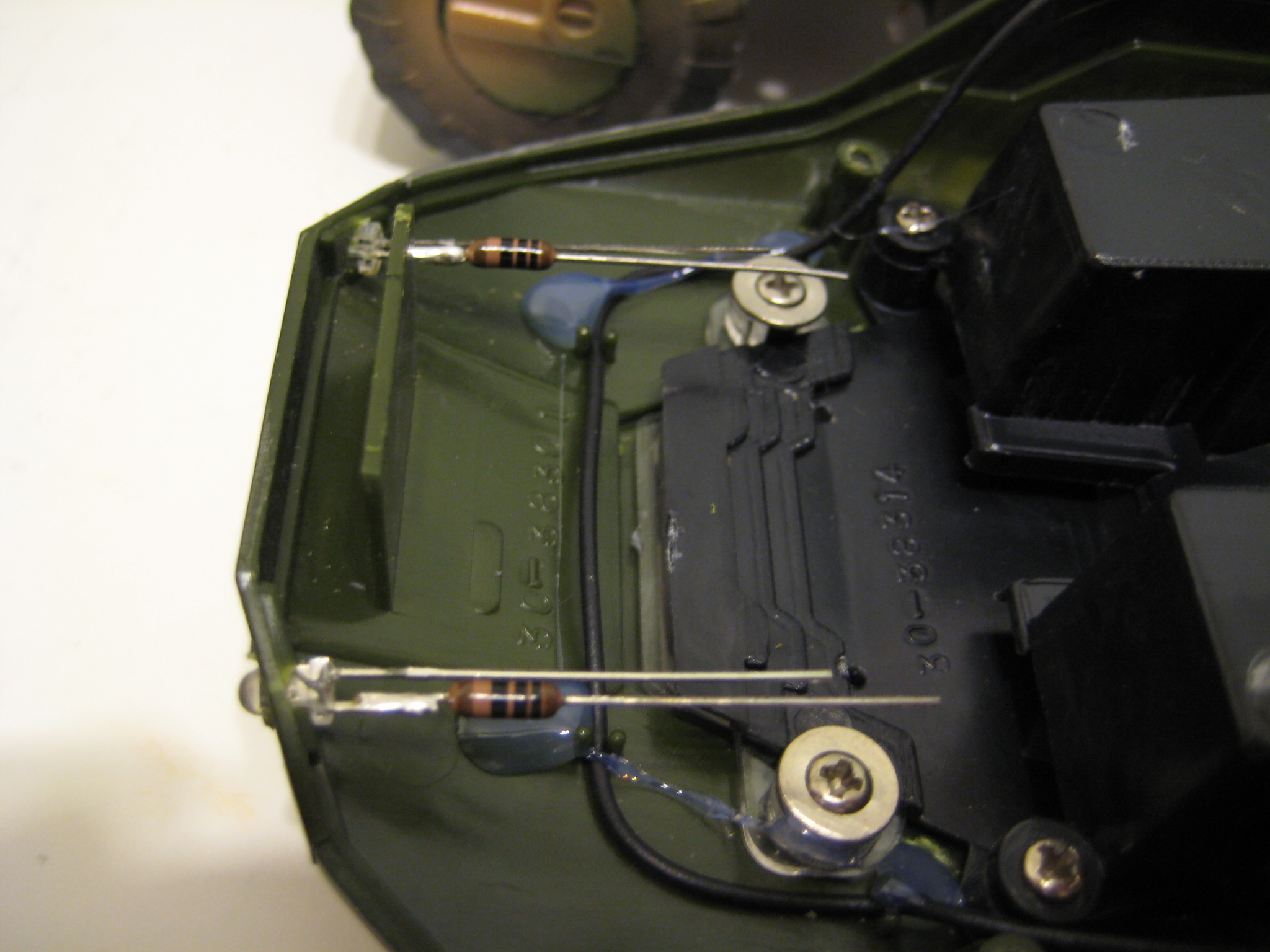
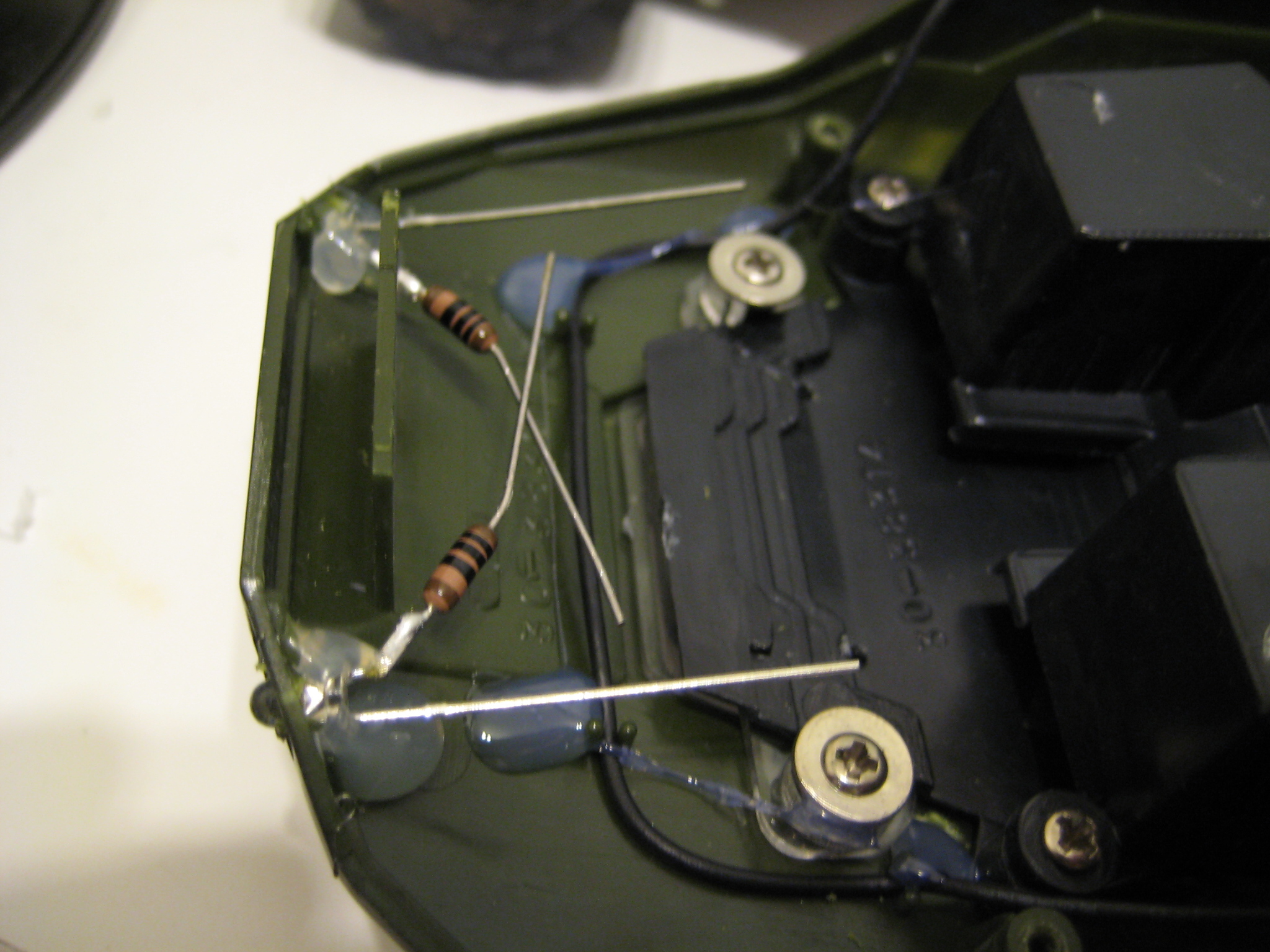
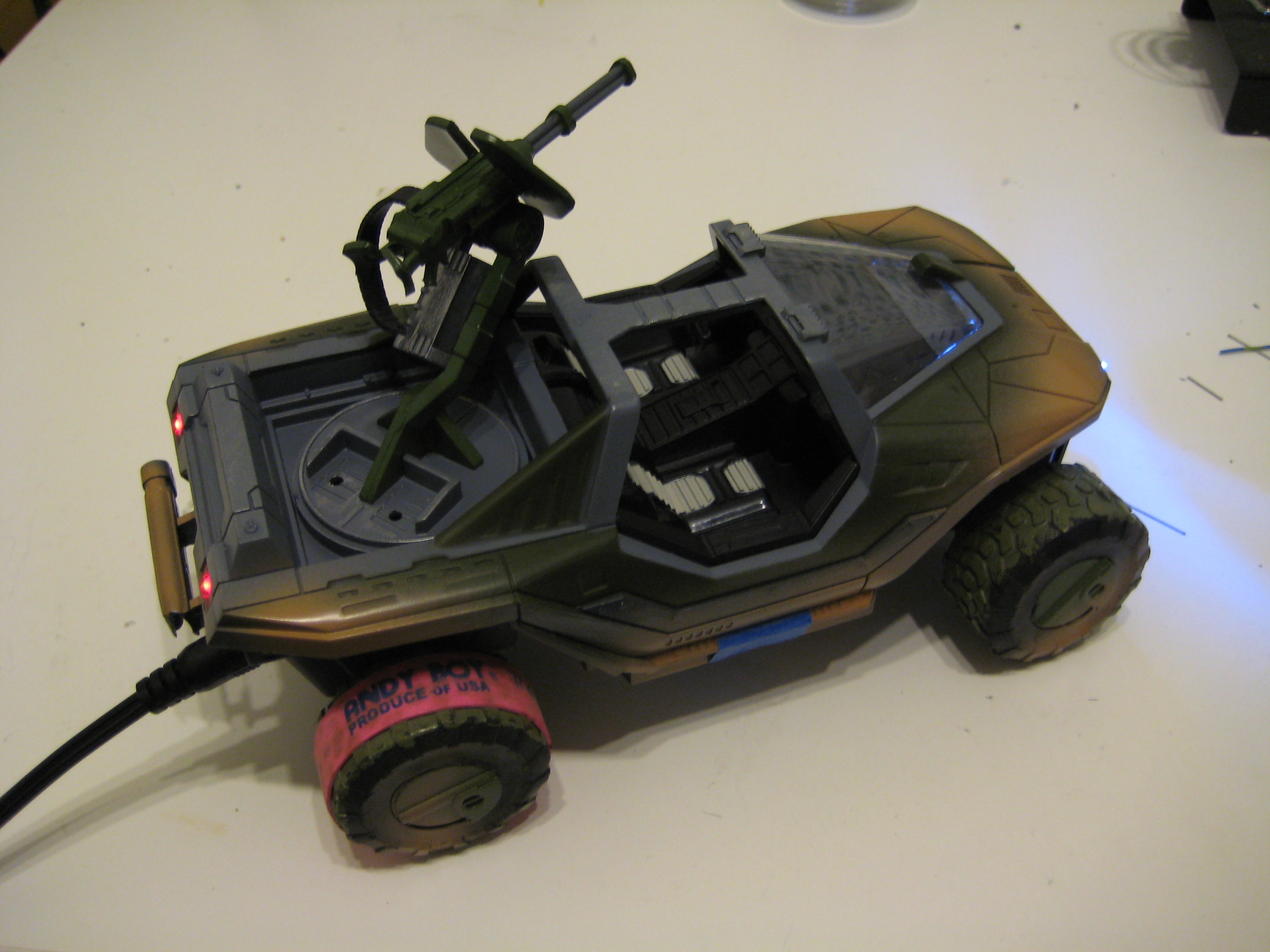
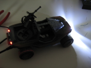
I used 3mm (T1) size LEDs for the head and tail lights. I used the Dremel rotary tool to drill out holes in the top shell. Sadly the drill bit I used wasn't labeled, so I don't know the exact size - it just looked about right. The LEDs were a push-fit, and I glued them in with a hot-glue gun.
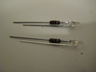

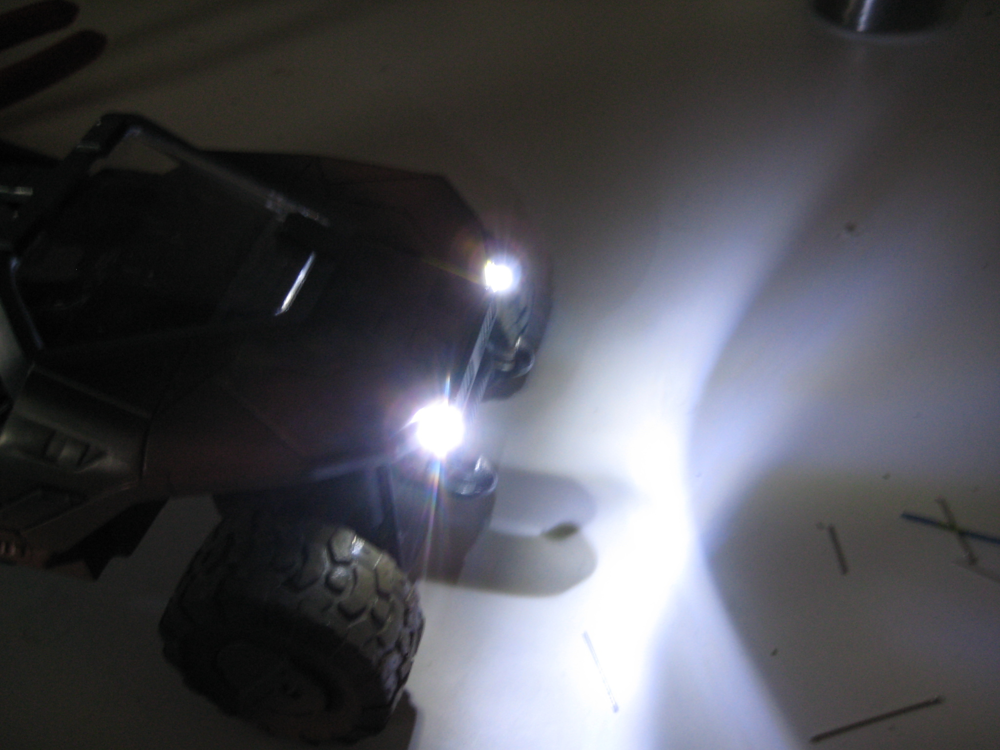
One issue with the lights was voltage supply. The LEDs of the tail lights are red - this gives them a forward voltage of 2.0V. With a five volt supply I can wire two of them in series with a relatively small resistor and get a nice glow. The white LEDs have a forward voltage of 3.3V. I felt they were too dim when put in series, so I added 100 Ohm resistors to each and wired the pair in parallel.
I also had to knock out some chunks of plastic from the bottom half of the 'hog so the new blobs of glue and wire wouldn't interfere when I closed the case back up. (Forgot to take a photo of the work in the back.)


Hey, it all works. First try, too.

And that's it! The two halves don't quite fit together anymore, for reasons I have yet to ascertain - nothing that a little brute force and ignorance won't fix though.
For some reason the remote doesn't have nearly the range that it once did, despite the reattached antenna. I suspect its due to the proximity of the lighting wiring to the antenna wiring.
One interesting glitch I discovered with extended use: after a few minutes of tooling around, the lights will dim dramatically when the 'hog is accelerating. At first I thought the battery was going flat (odd, given the capacity of the cells and the rate of discharge they were rated for), but I noticed the issue would disappear if I left the 'hog alone for a few moments and then tried again. At least, it disappeared for a few seconds of movement before coming back again. I remembered that the 'hog gave off a hot-metal smell after use; I had always chalked it up to the motors, but on a whim I did some experimental prodding. Turns out the area around the 7805 regulator gets extremely warm. When somebody hits the go button that motor in back must suck down a hell of a lot of current, to the point where it maxes out the 1 amp provided and heats up the device to the point where the thermal cut-off kicks in.
A couple solutions exist: put in a higher current regulator and/or add another regulator in parallel, heat sinks on all of the above (almost impossible given the limited space inside the case), or implement some kind of power switch system where the logic board drives transistors or relays that connect the motor directly to the battery.
Alrighty. I think this project is going on the shelf for a while - I have other things baying for my attention.
DISCLAIMER
All content is owned by its respective creators/licence holders.
Unless otherwise stated, everything else: Copyright © 2010, Chlazza