iPod Ultradock (Breakout board with EVERYTHING)
 A 1st gen iPod Nano and some variant of the iPod Photo line appeared in my cruft heap recently. Besides the batteries of both being (mostly) dead, some of the buttons being a bit gummed up, and the drive in the Photo being half the size advertised on the case, they are in relatively good shape.
I really like the 1st gen iPod Nano's form factor, but I dislike the socket Apple put on all the iPods after the 1st gen Classic. I mean, I see where they were coming from - they wanted a smaller part than a full sized Firewire socket and if they could fit more pins in to boot, hey, that's great - but the connector they selected proved to be elusive for the average hobbyist. Well, until recently at least: This group was started to manage a group-buy by denizens of the iPodLinux forum - as I understand they locate and import parts (in bulk) directly from manufactures in East Asia and resell them individually as a service to the community. In addition, Sparkfun carries a somewhat smaller selection of components.
Sourcing the iPod connector was really the hardest part of this project. The rest is tedious, but straight forward (if you have datasheets - more on that in a second).
(For the record, I am aware of Engadget's Super Dock project (part 1, 2, 3, 4) - I stumbled across it after I had the bulk of my project done. This isn't just a copy of their work.)
Resources and Credit
Sparkfun - iPod Connector Male Style 1
Pinouts.ru - Apple iPod and iPhone (2g, 3g) Dock Interfaces pinout (Спаси́бо!)
Allpinouts.org - Apple iPod - iPhone dock Connector Pinout
Parts
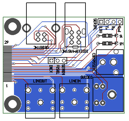
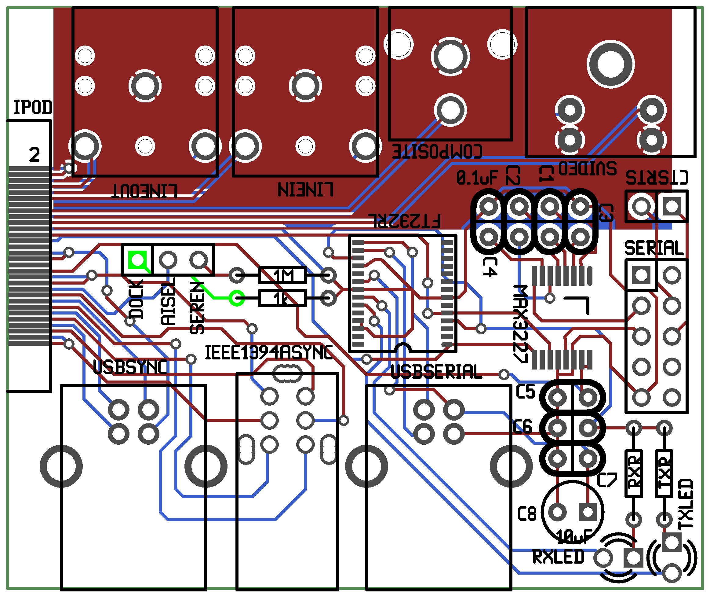
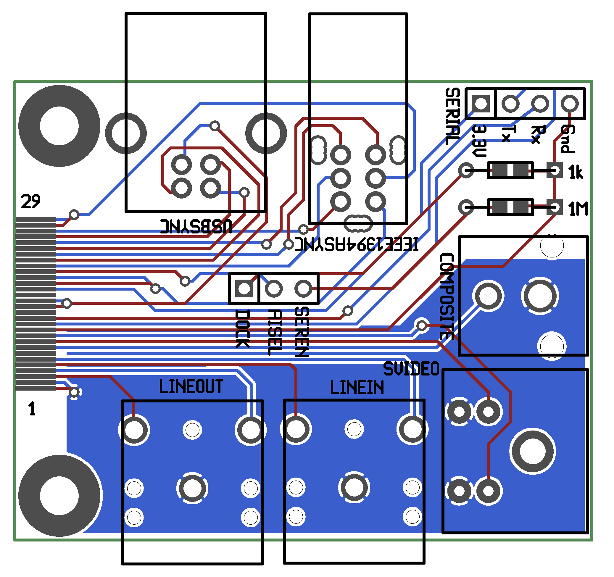
Sourcing and building a footprint for the iPod connector is the major hurdle for this project. In theory, since this is just a breakout board, the rest is just layout.
Well, sadly, gEDA PCB doesn't have footprints for some common parts like mini-DIN or USB-B receptacles. Thus, the next biggest hurdle was footprints for the myriad of parts that needed to go on the board.
iPod Plug:
I originally used Sparkfun's iPod Connector Male Style 1 (DEV-00633). I'll be honest: there was some shock at the price, but I was already picking up some other bits and pieces from Sparkfun and didn't want to pay shipping for a separate order from another supplier.
The Type D connector that the Group Buy Supplier carries appears to be identical to the Sparkfun connector I got, minus the cover, assorted hardware, and almost two USD in price.
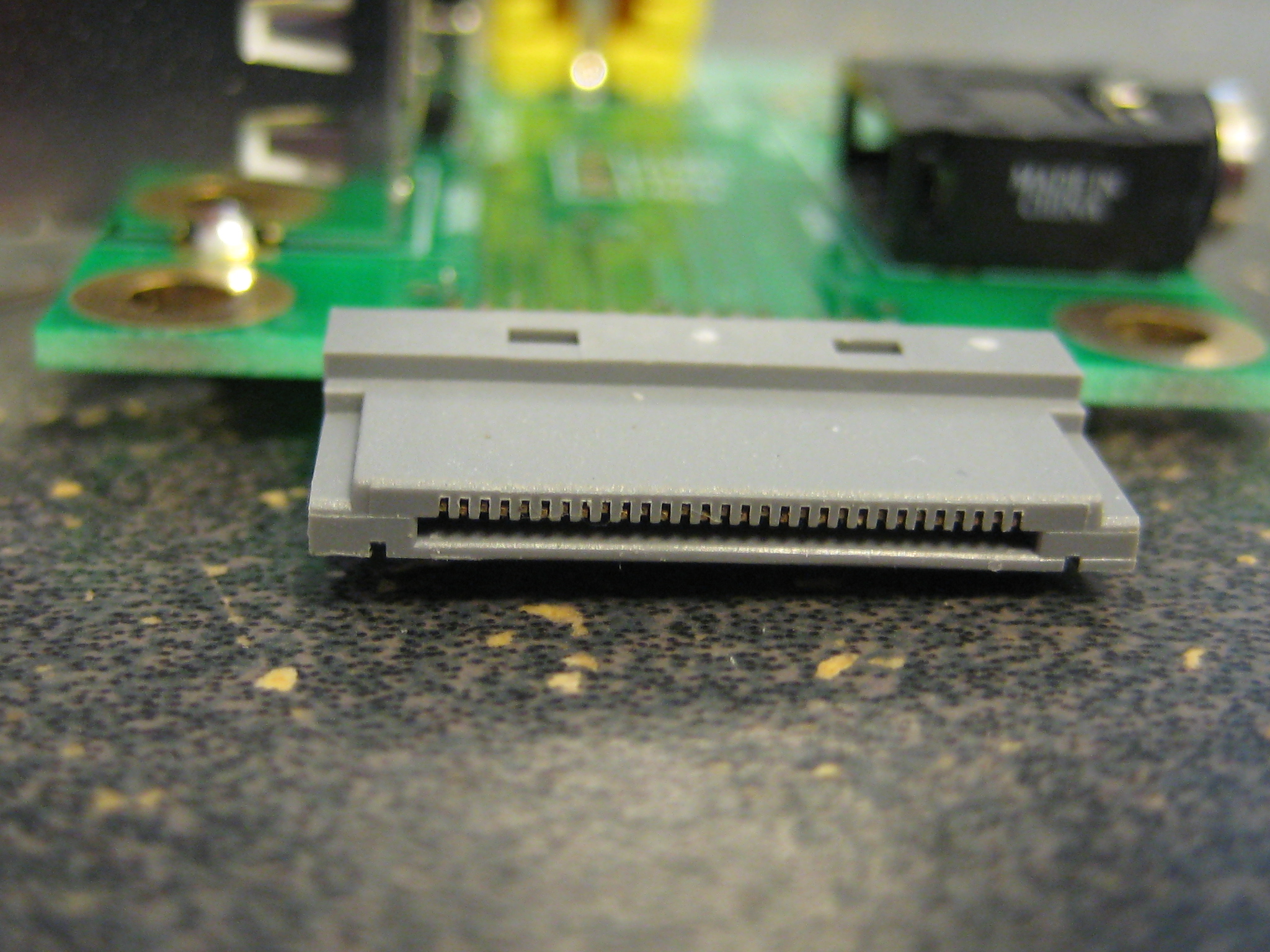
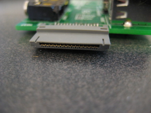
Unfortunately, neither supplier had a datasheet that detailed the part footprint, so I wound up measuring the pins by hand. The Engadget project mentioned above was useful in checking my work, particularly since they seem to be using the same connector as me.
Engadget calls the pin pitch at 0.0195 inches which works out to be ~0.4953mm - I rounded that up to 0.5mm. Since the pins alternate, top/bottom, that puts the distance between pins on one layer at 1mm pitch - this matches my rough measurements with a ruler and a test with a DDR2 DIMM (which have a pin pitch of 1mm). The pin width appears to be significantly less than 1mm, maybe even 0.5mm. Engadget lists 0.016" (0.4064mm) as "the right width". Engadget also claims to have made the pads 0.140 inches (~3.556mm) long. Ruler puts the full pin length at ~3.5mm. In my numbering scheme, facing the end of the plug (not the socket on the iPod) with the pin layer on the bottom/down, pin one is at the far left (this matches the layouts detailed in the links in the Resource/Credit section above).
USB-B Right Angle Receptacle, Through Hole:
I got a whole tray of these while dumpster diving, but no datasheet. I checked out a few datasheets on Digikey from various manufactures - to my untrained eye it looks like the footprints of these sockets are standardized. I found a datasheet that covered a subset of the Molex 67068 series of USB connectors that seemed to be the most informative of them all, and worked off of that. (Datasheet, local copy)
Four Pin miniDIN (S-Video):
This was the simplest connector in the whole project. The de facto standard S-Video connector seems to be a generic four pin miniDIN. The parts I bought had one mounting pin and four data pins in an easy-to-layout grid. Nothing special here.
I selected the CUI Inc. MD-40S (datasheet, local copy) - CP-2440-ND on Digikey.
3.5mm (1/8") TRS connector/stereo phone mini-jack:
All the serious audio equipment I've seen uses either RCA or XLR plugs and jacks (except for some 1970's British stuff that used some DIN derivative). I went with the more pedestrian TRS connectors because TRS-to-RCA converters are easy/cheap, I figure most people are going to be plugging in spare computer speakers/mics, and the mini-jacks take less board space.
I used another CUI Inc. part, the SJ1-3523N (datasheet, local copy) - CP1-3523N-ND on Digikey.
IEEE 1394a Right Angle Receptacle:
A not-so-straightforward footprint. Two items of note: I couldn't just drill holes for the support pins - if I dilled a hole with a diameter matching the largest dimension of the support pin, the hole would overlap some of the data pins. The solution was to drill several overlapping (smaller) holes in a row and hope the PCB fab house didn't complain. I also had to tweak the mask and pad diameter for all the pins - I try to give a generous allotment of space to ensure easy soldiering, but the pins are close enough together that my usual diameters were in violation of the clearances set by the fab house.
I used the 693-006-621-003 connector from EDAC (datasheet, local copy) - 151-1087-ND on Digikey.
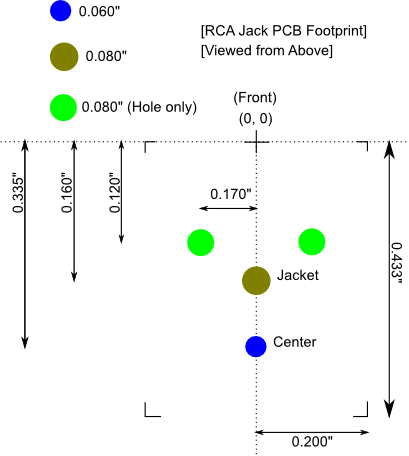
RCA Jacks:
Composite video is traditionally delivered through a single RCA jack, normally colored yellow. Some electronic devices (notably cameras) use a 3.5mm (1/8") mini-jack connector for video or audio/video out. To avoid confusion (and because I had some laying around) I decided to go with the RCA jack. The only problem I ran into here was that I had no datasheet for the parts I had. I got out a ruler and went to work:
 Maxim IC MAX2337 SSOP:
Seems like everybody and their grandmothers use MAX232 ICs when they want to drive a serial port with TTL levels. Not the best choice for this project, as the MAX232 has an extra transceiver that we don't need and won't run off the 3.3V the iPod provides. After some poking around on Maxim IC's website I settled on the MAX3227 - it uses a 3.3V or 5V supply, uses 0.1uF caps (which I have a metric fuck-ton of), has one Tx/Rx pair, comes in a SSOP package (yay, board space, boo, tiny pins), and has a fancy autoshutdown feature which saves power. It's also 0.50USD cheaper than a straight MAX232 from Maxim (per 1000 units; Digikey sells individual MAX232 PDIPs from TI for about the same price). Note that the MAX3226 appears to be identical, with the exception that it has a guaranteed data rate of "only" 250kbit per second while the MAX3227 has a guaranteed rate of 1000kbit per second - so I figured 'why not'? To save space and reduce cost I put a 5x2 pin header on the board instead of a full DE-9 jack.
FTDI FT232RL SSOP:
A Mac using friend of mine pointed out that Macs don't have dedicated serial ports, nevermind DE-9 connectors. FTDI makes a line of popular TTL-serial-to-USB chips - adding a FT232RL to the board was relatively trivial. The only downsides are that there are now more tiny pins to solder, and FTDI doesn't appear to do free samples (it's about 4.50USD per chip from Digikey).
Files
All files in this segment are in gEDA PCB format.
iPod board-edge connector footprint: ipod_30pin_straddle.fp
USB-B Right Angle Receptical footprint (generic): usb-b_rightangle_receptical.fp
Four Pin miniDIN (S-Video) footprint: svideo_minidin.fp
3.5mm (1/8") TRS Connector footprint: phonejack_3.5mm_stereo.fp
IEEE 1394a Right Angle Receptacle footprint: 1394a_rightangle_vertical_receptical.fp
RCA Right Angle Jack footprint: rcajack_rightangle.fp
All file in this segment are in gEDA gschem format.
FTDI FT232RL (SSOP) symbol: ftdi_ft232rl_ssop.sym
Maxim IC MAX3226/MAX3227 (SSOP) symbol: max3227-3227.sym
IEEE1394a 9-pin connector symbol: IEEE1394_9pinconnector.sym
iPod connector symbol: apple-ipod_connector.sym
USB-B Receptacle symbol: usb-b_receptical.sym
Ultradock V1 (formerly Rev0) [Deprecated]
Files
 Gerber files (back/front copper/mask/silkscreen, outline, drill file) for board: ultradockV1.20100608.zip
Layout (gEDA PCB format): ultradockV1.pcb
Schematic (gEDA gschem format): ultradockV1.sch
Notes
[2009-10-21]
My boards shipped from BatchPCB!
[2009-10-28]
Boards received. Promptly tried to solder the SSOP parts. Failed horribly.
I think I got the MAX3227 chip off-kilter on the pads. I managed to lift a pad when I was trying to tack down the FT232RL, and then it popped out of my hemostats and fell into the dense undergrowth of junk in my lab. Haven't found it yet - ticks me off, given the price.
I filled in the rest of the board, mostly. The RCA jack footprint needs bigger holes for the mounting pins, the barrels on the 3.5mm TRS jacks aren't quite flush with the board, and Digikey sent me a wrong part (machine pin headers labeled as IEEE 1394A sockets) but other than that everything went in fine. The USB-B receptacles are a dream to solder - the angled mounting pins snap right in and hold the part flush with the board. Then you just heat them up and drown them in solder - no tape, glue, mess, or fuss.
[2009-11-09]
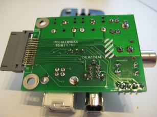
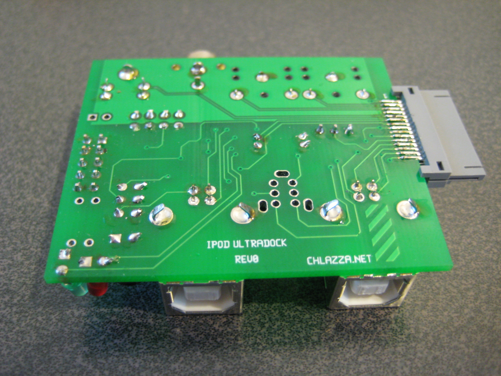
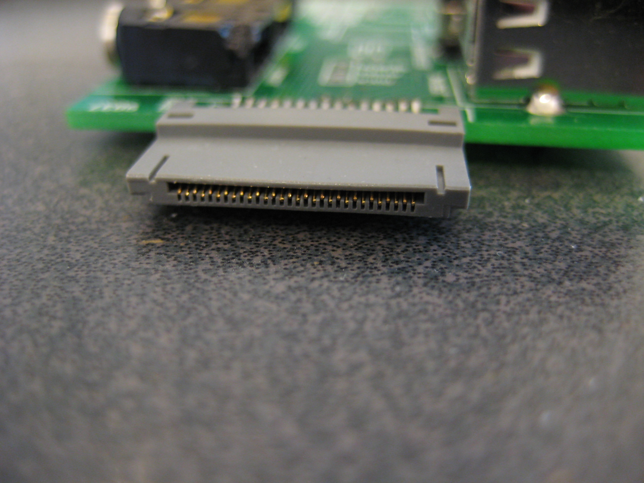
Looks like I flipped the iPod socket footprint on the board.
Boards should still work (I hope - they haven't been actually tested yet), but the component side of the board is on the opposite side of the iPod face.
Not that big of an issue (TIWIIRZ) but I wish I had noticed this before I soldered down the $4 iPod plug in the wrong orientation.
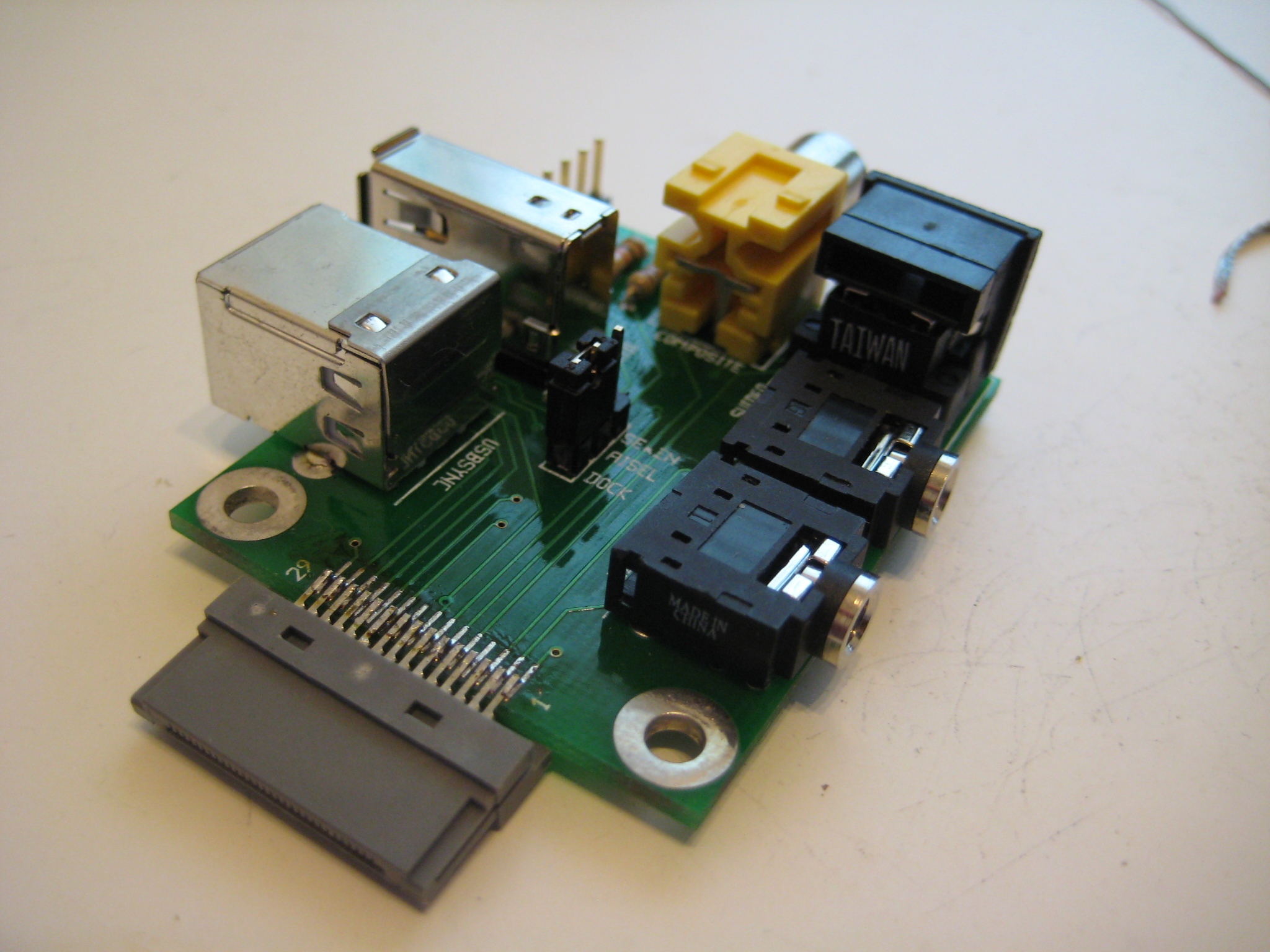
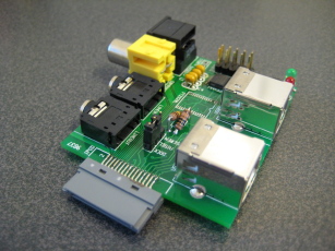
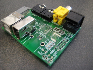
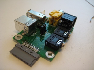
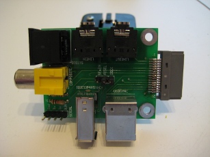
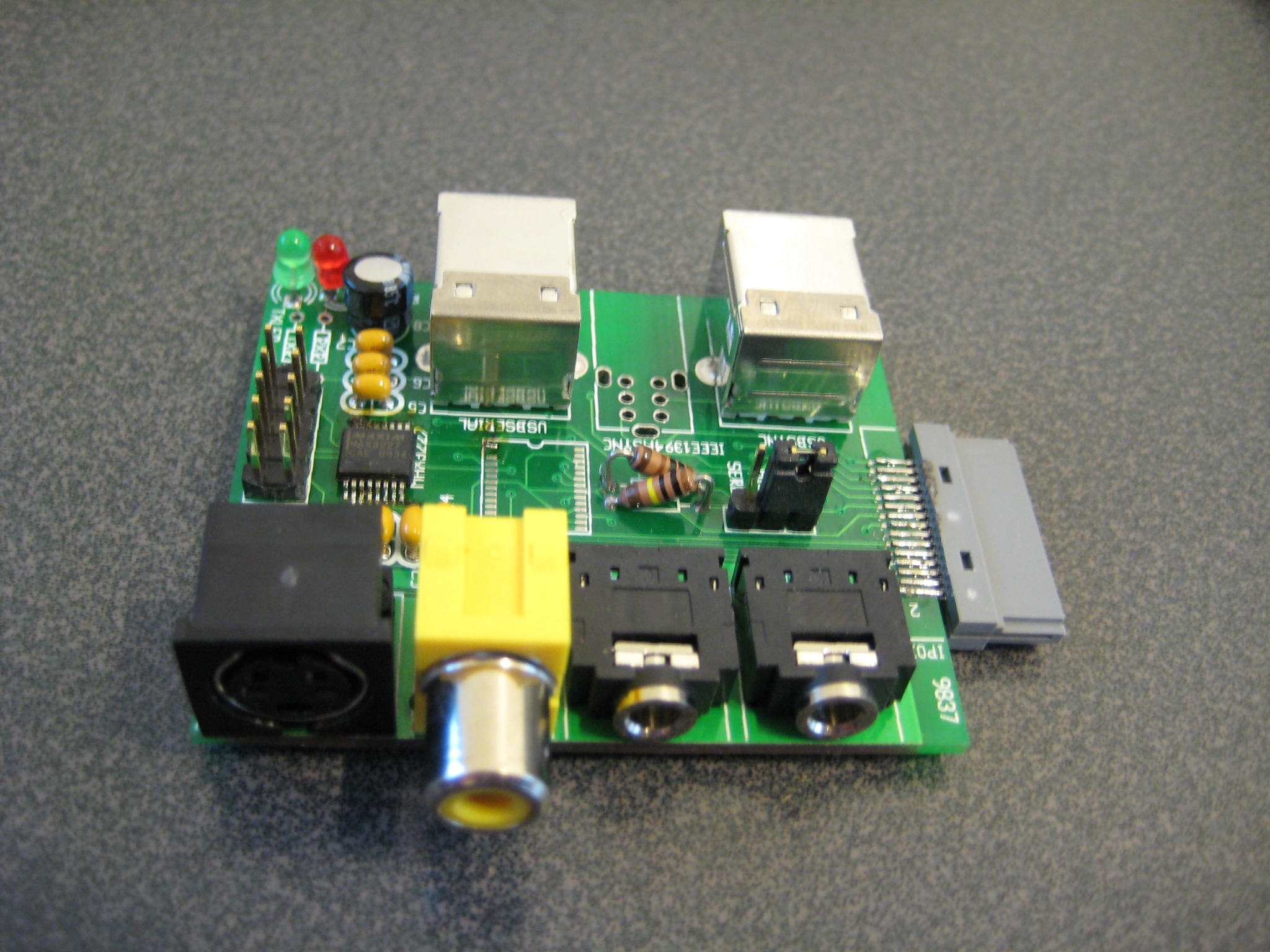
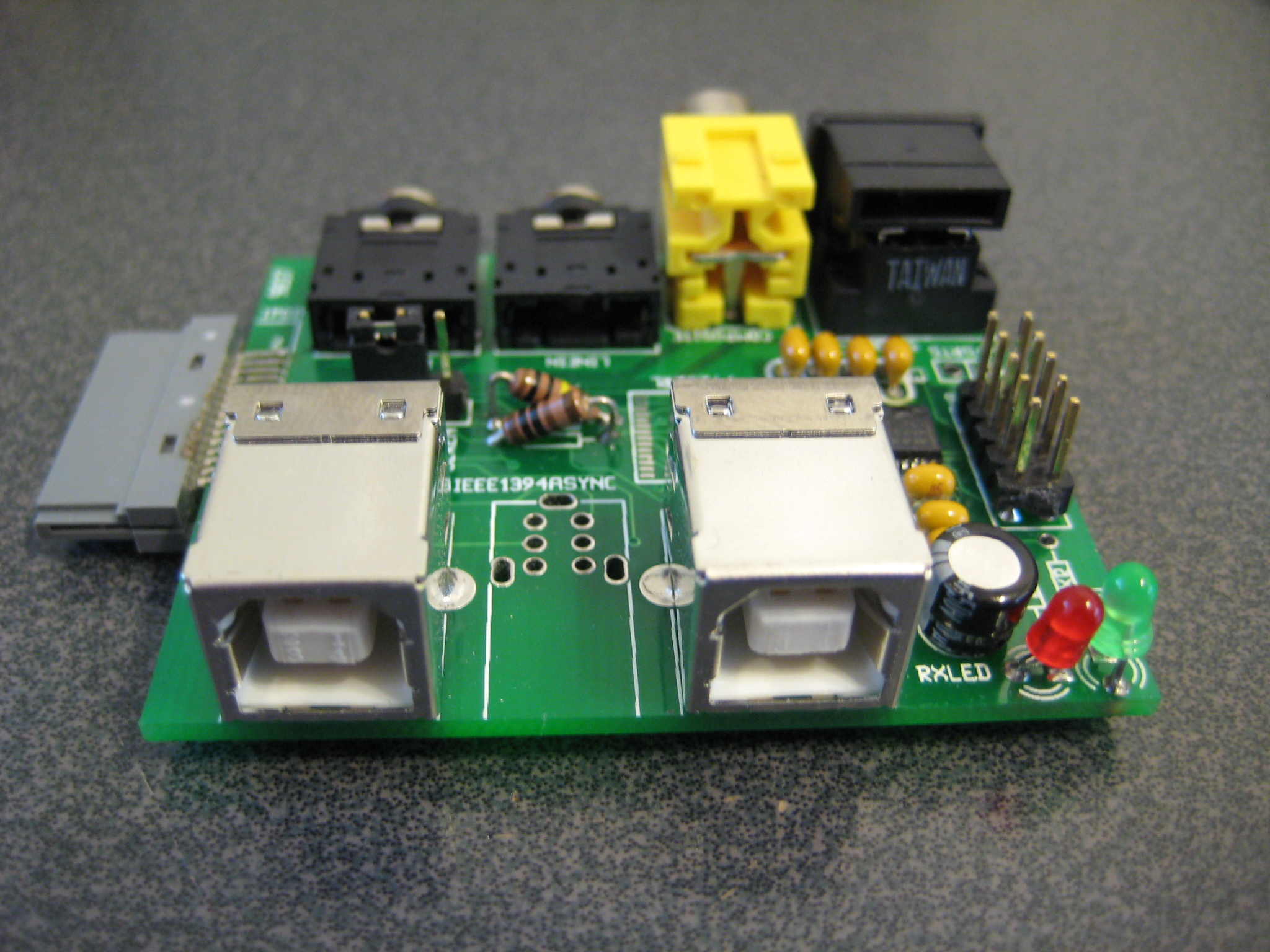
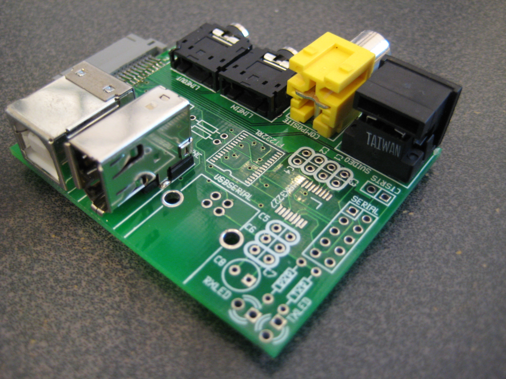
Here are some glamor shots of the stuffed board - click to embiggen. NOTE: It is missing a few parts and the iPod plug is attached incorrectly!


 [2010-01-27]
Somewhat put off at the price of the connectors at Sparkfun, I stocked up on connectors from the Group Buy group mentioned above.
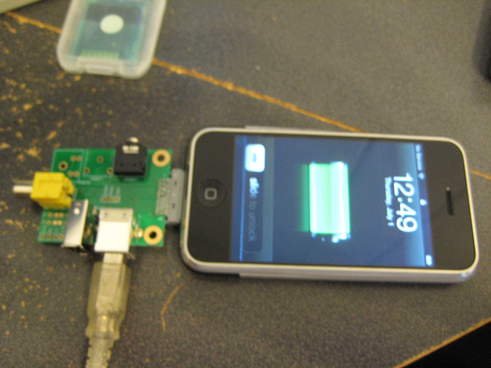
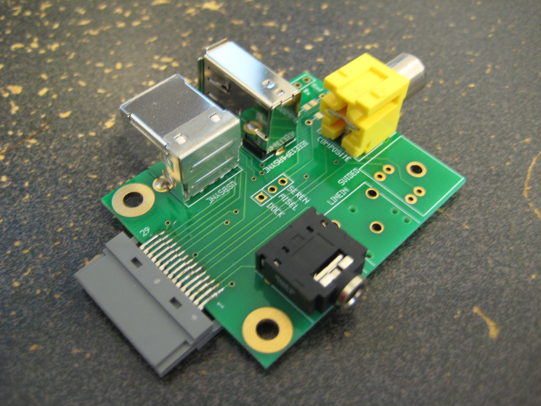
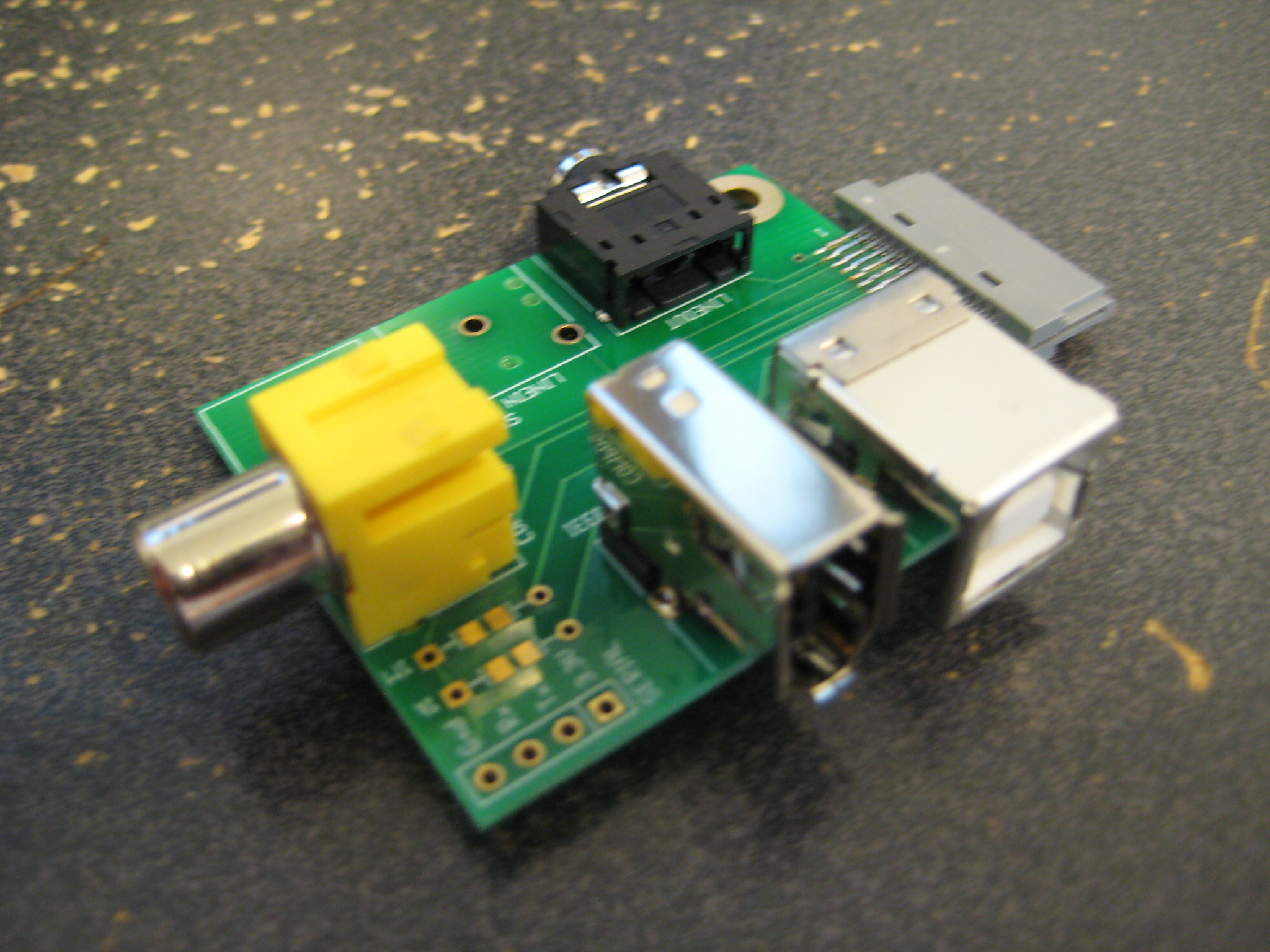
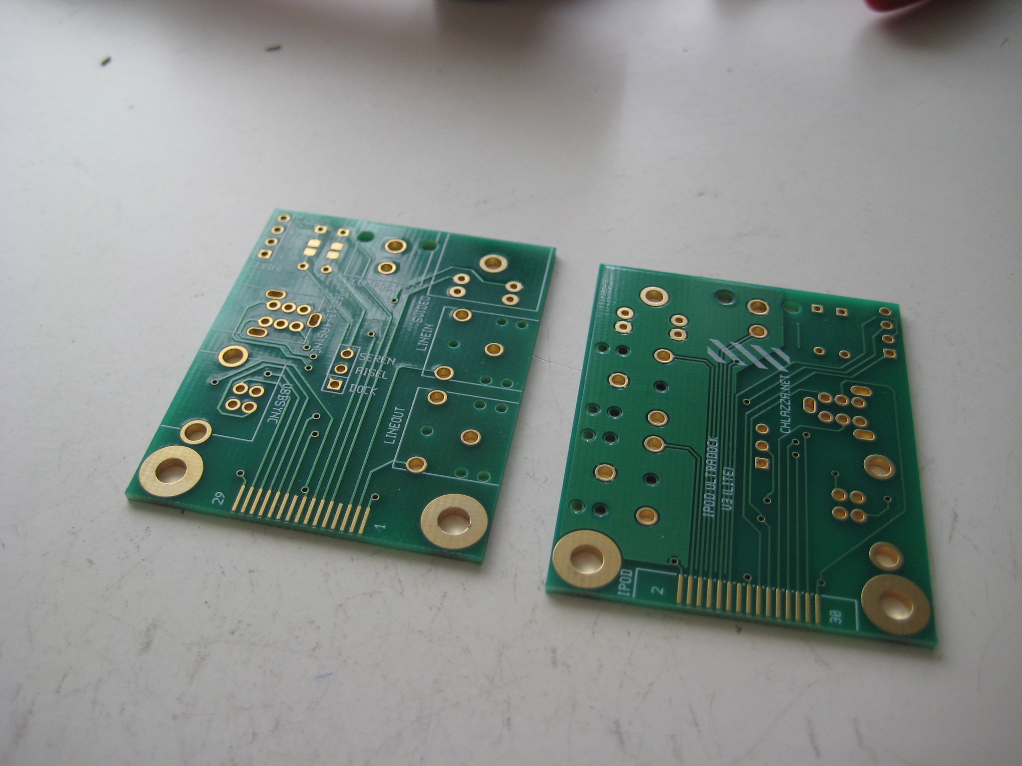
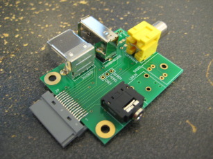
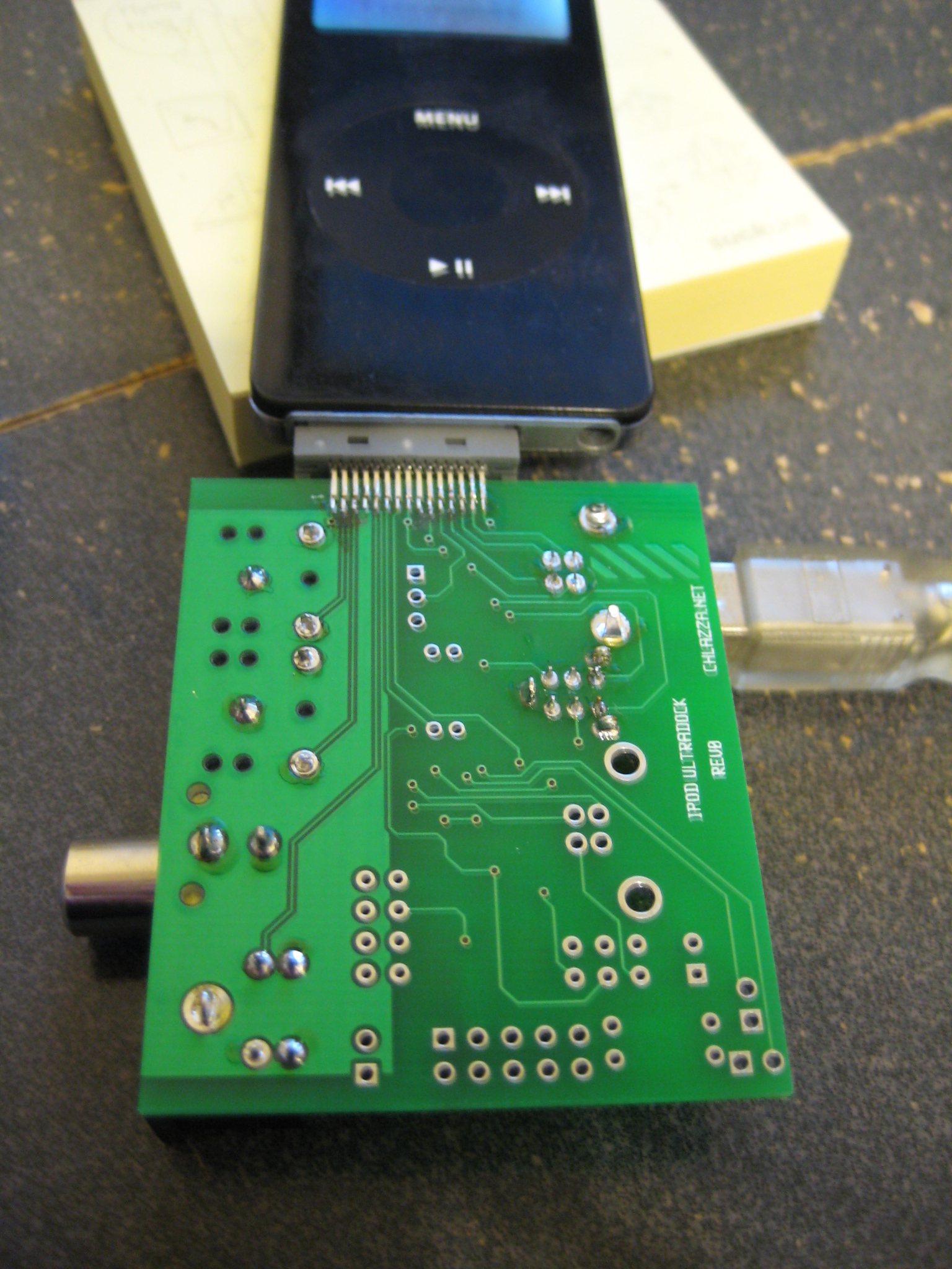
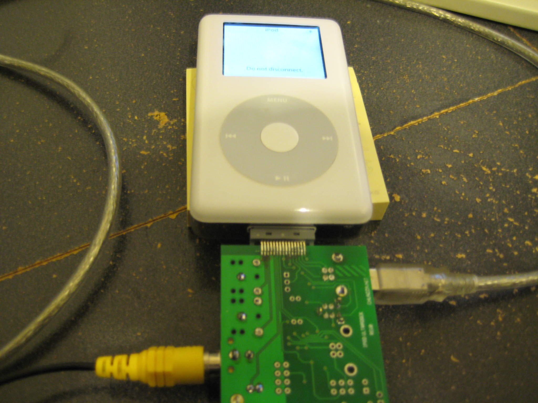
I was unable to successfully remove the iPod connector from the previous board without wrecking both the connector and its footprint on the board, so I grabbed one of my spare boards and did a minimal build-up. Note the orientation of the iPod connector on the board this time around:

Whaddya know? It works:


Well, at least the USB sync and Composite Out do. I didn't test the rest as the USB sync was enough to bootstrap the iPod Photo via the iTunes iPod Restore function and return it to working order.
More testing is planned, and then I'll be prototyping Rev0.1 (see below).
[2010-06-08]
The diameter of the RCA jack mounting holes is/was a known issue. I fixed the PCB footprint for the jack, but somehow failed to update all my other layouts that used the jack. Should be fixed now.
Also, updated version system. Details in 2010-06-08 update in Ultradock Lite section.
Ultradock Lite - V3 (formerly Rev0.1 and Rev0.2)
Files
 Gerber files (back/front copper/mask/silkscreen, outline, drill file) for board: ultradockV3.20100608.zip
Layout (gEDA PCB format): ultradockV3.pcb
Schematic (gEDA gschem format): ultradockV2.sch
(Note: The V2 schematic is still relevant, just the layout has changed.)
Notes
[2010-01-30]
Man, fuck SSOP parts.
In my new version I just broke out the serial pins to a four pin header (3.3V, Tx, Rx, Gnd). The end-user is going to need another board to convert the signals to the appropriate levels/format, but serial comm has no direct end-user use in the original Apple-provided firmware anyway. This also has the added benefits of making the board smaller, simpler, and cheaper to produce.
The iPod connector footprint has also been flipped so the component side of the board is on the same side as the iPod face.
[2010-05-05]
Updated the layout - now with more ISO262 M3 screw holes! Also moved the serial pins to a more accessible location. Also added footprints for 0805 resistors for the function select jumper.
[2010-06-08]
The diameter of the RCA jack mounting holes is/was a known issue. I fixed the PCB footprint for the jack, but somehow failed to update all my other layouts that used the jack. Should be fixed now.
Version system now reflects number of times the board has been modified and then fabricated, instead of a semi-arbitrary production number and fabrication iteration.
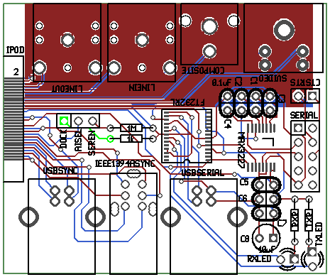
I fabricated a couple of V2 boards recently:
The RCA jack mounting post issue was discovered, and I realized that the board thickness is not ideal for the iPod connector. Composite and S-Video output is noisy and unreliable; I tracked it down to the contacts inside the iPod connector being pushed up/down by the force exerted on them by me trying to wedge the connector onto a board that is just slightly too thick. USB Sync and Line Out appear to work fine. I could charge my iPod Photo off of Firewire, but couldn't get it connect to the computer - I suspect the 'pushed contact' problem noted earlier. I was unable to test the Line In socket as (apparently) none of my iPods support recording.
[2010-07-09]
Alright, I think this is it for this project.


Gold plating? Yup. I got a stack of boards made at MyRO PCB. BatchPCB tins everything, which leaves a comparatively uneven surface and which makes it a bit more difficult to solder fine-pitch connectors. While I was at it I also ordered the boards with a thickness of 1.3mm (compared to the 1.6mm boards that BatchPCB makes) - which appears to be the ideal thickness for the iPod connectors.
(Holy smokes, all that took ten months?)
DISCLAIMER
All content is owned by its respective creators/licence holders.
Unless otherwise stated, everything else: Copyright © 2009-2010, Chlazza
 Gerber files (back/front copper/mask/silkscreen, outline, drill file) for board: ultradockV1.20100608.zip
 [2010-01-27]
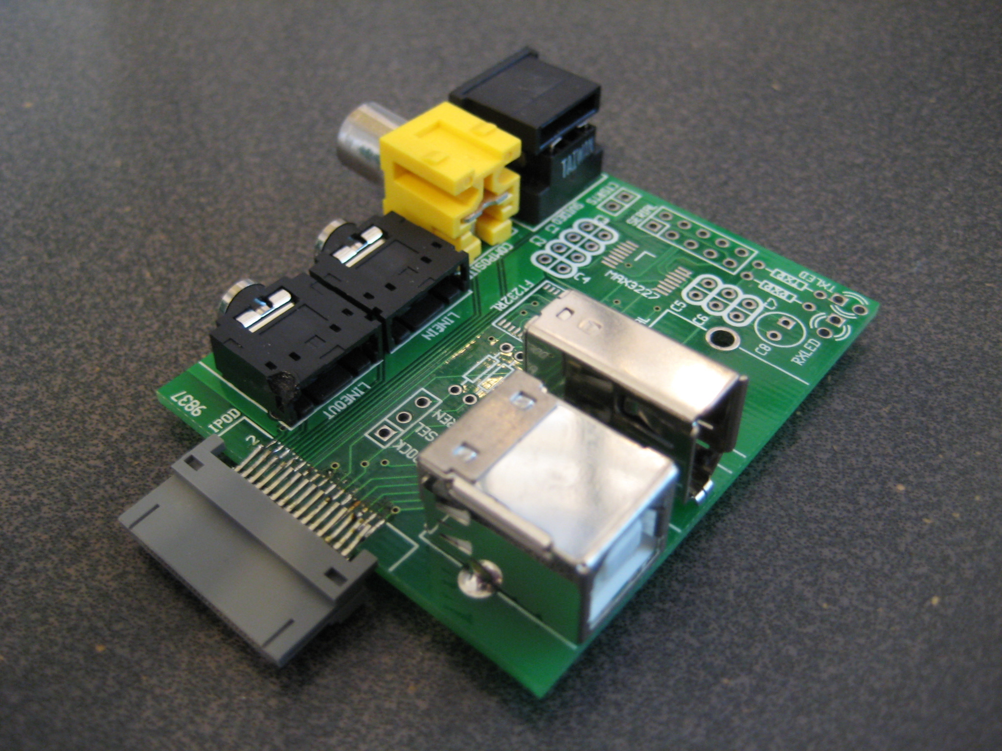
 Gerber files (back/front copper/mask/silkscreen, outline, drill file) for board: ultradockV3.20100608.zip