WRT54GL Serial Port Breakout Board
 It has been said[who?] that necessity is the mother of invention. That is definitely the case here.
A few months ago I was trying to put together a Quality of Service solution for my home network. Time critical traffic (read: Diablo II) was routinely getting mangled by large data transfers. For some unfathomable reason the Apple Time Capsule that we were using as a switch/AP has no QoS system whatsoever, and our DSL modem was equally unequipped. I had gotten my hands on an infamous Cisco/Linksys WRT54GL router a while back and decided to try out some of the available Linux distros to see if I could get something hacked together for my purposes. The project eventually went nowhere, but I digress. In the process I hosed the settings and had to crack open the case of the router and solder a connector on the mainboard inside and rig up a UART/USB adapter so I could get at the serial console. This connection was delicate at best.
There must be a better way, I mused. A quick Google search indicated that many people have rigged up external serial ports to their routers but all the solutions I found were permanent and hacky - lots of hot glue fixes, lots of soldering wirewrap wire.
Somebody should really build some kind of adapter board for this, I thought to myself.
From the start, there was really no question about the general design. I would need USB connectivity at least, and a real serial port would nice. The only big decision came with the number of serial ports: the WRT54GL has two on its JP2 header. One is the default serial console and the other is anything you want. I wanted to have the option to connect to both, however that proved expensive - the USB/UART bridge chips I originally envisioned would come to about 10USD alone.
I also wanted to fit the whole adapter inside the case of the router - there is a rather large rectangular cutout in the mainboard and plenty of vertical space but it turns out there wasn't enough space on the front panel to squeeze in all of the envisioned connectors. I split the board in half (which is why some documents here reference the 'Small' design) and came up with a daisy chain system. I eventually dropped that idea as well in favor of a group of jumpers that allows the user to select which serial port is connected to which output port. (Note that the adapters can still be chained, but the user needs to manually set the serial port being used by each connector.)
Maxim IC is semi-famous for its RS-232 level converters - I went with the MAX3232E, which is about as generic as they come but has extra protection against static discharge. I used a DIP package with a socket so the user (well, me) can pull the chip out and directly access the signals from the router or DE-9 socket without having to fiddle with the ribbon cable or employ some creative soldering.
Selection of the USB bridge was a bit more involved.
FTDI is arguably the market leader in this area but the FT232RL chip comes only in the SSOP package (which I hate soldering) and costs almost 5USD each in small quantities. A brief market investigation revealed scant-few alternatives. I briefly considered a couple of non-commercial projects that emulate the USB protocol on general purpose microcontrollers, but didn't feel like writing the code. (Although that has a good chance of becoming a future project.) The company Microchip is known for its microcontroller line, but has quietly released a UART/USB bridge chip: the MCP2200. It has some distinct disadvantages compared to the FTDI offering; specifically it doesn't appear to automatically adjust the baud rate (requiring the use of a Microchip-supplied utility and a computer running Windows XP) and requires an external oscillator/crystal. On the other hand, it comes in an SOIC package and is about half the price of the FT232RL.
I had intended to get FT232RLs, but Digikey was out of stock that day, so I went with the MCP2200s.
I also had plans to build a proper metal case for the WRT54GL and breakout board, but I doubt that'll ever materialize.
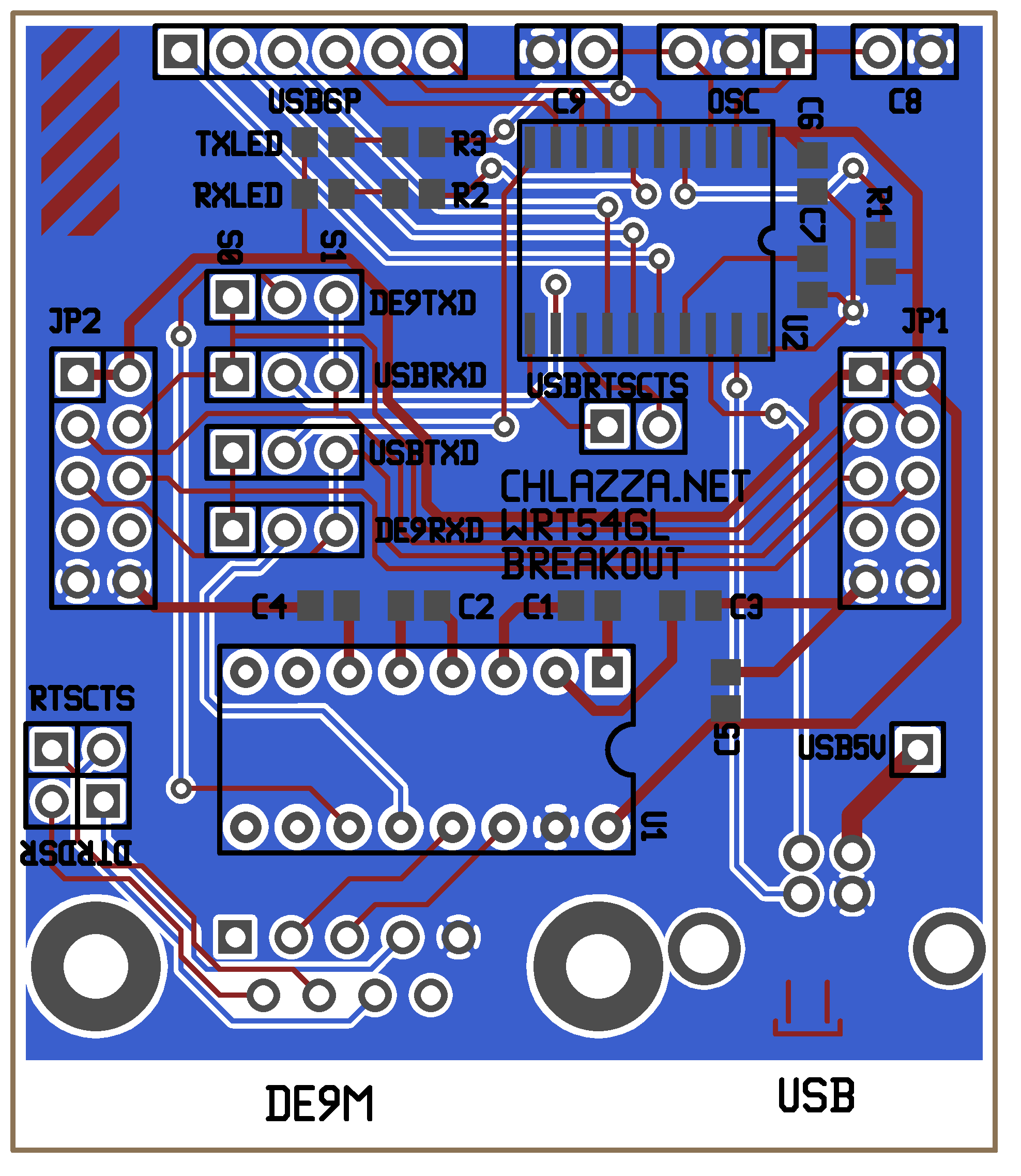
 Gerber files (back/front copper/mask/silkscreen, outline, drill file) for board: wrt54glbreakout_v2b.zip
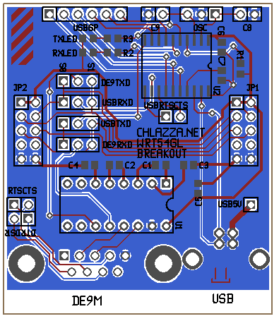
Layout (gEDA PCB format): wrt54glbreakout_mcp2200_small.pcb
Schematic: gEDA gschem Format / Encapsulated Postscript / PNG
Microchip MCP2200 UART-to-USB IC (datasheet, local copy)
Maxim IC MAX3232E RS-232 Transceiver (datasheet, local copy)
[2011-08-14]
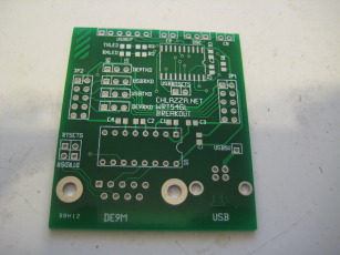
I have most of the parts and have ordered the boards.
[2011-10-23]
Hey, look what I've had on my desk for the better part of a month!
I'd say something like 'oh, I've been too busy to work on anything' but I'm pretty sure you guys don't give a flip, amirite?
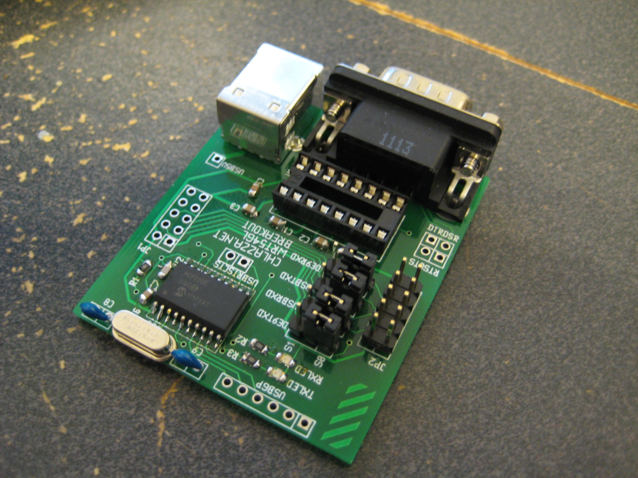
Those 0805 parts are a bit fiddly; they're pretty much as small as I can reliably handle. They're not overly frustrating to work with, but when I pull the parts box out I always find myself a bit incredulous that I can actually solder them.
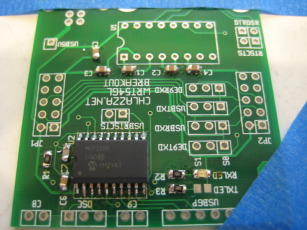
Final product. Missing the MAX3232E chip, though - I seem to have misplaced my pants the chips I ordered.
 [2011-10-30]
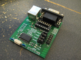
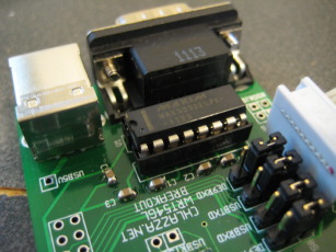
Yeeeah, so the header footprint is upside-down.
Whoops.
(Ignore the jumper in pins 11 and 12 of the MAX3232E chip socket in the photo above - that's just me screwing around.)
Beyond that, though, does it work?
It sure does!
There is some setup involved however - as mentioned above the MCP2200 doesn't auto-detect baud rate of the incoming signal, and the Tx/Rx LEDs aren't enabled by default.
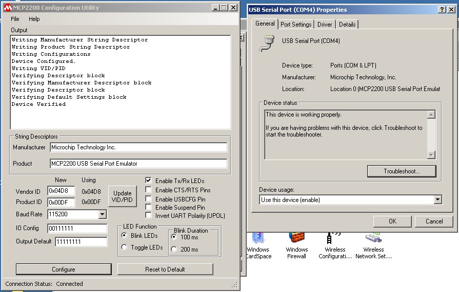
To configure the MCP2200 you will need to grab the drivers and configuration utility from Microchips website (or give this link a try, although it may have moved in the meantime) and a Windows machine to run the utility on. The configuration utility installer may install the needed drivers automatically.
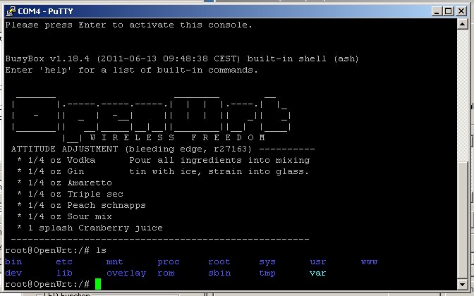
Once the computer is set plug in a properly assembled MCP2200 (you should see it appear as a serial device) and run the utility. The utility should automatically detect attached MCP2200 chips - check the status bar at the bottom of the window. (No word on what happens when a computer has multiple MCP2200 devices plugged in at once.) At that point you may make changes as desired. When ready to update the chip, hit the configure button and you should see some text scroll by in the output textbox (see screenshot above for an example).
In this case I set the baud rate to 115200 and checked the 'Enable Tx/Rx LEDs' option. Everything else was left as default. I then fired up PuTTY and checked the connection (115200 baud, eight bits, no parity, one stop bit).
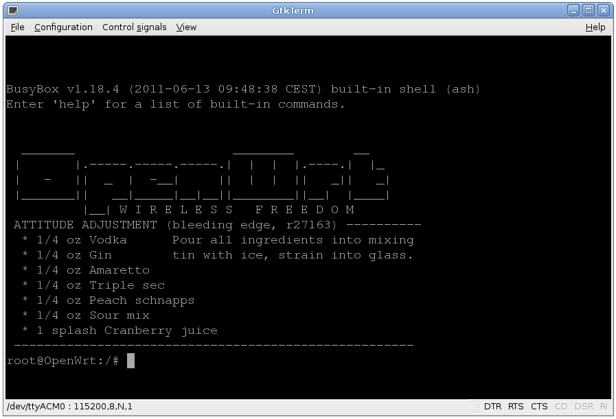
So does the adapter work with Linux? Once configured, yes. A reasonably modern Linux kernel will see the MCP2200 as a serial device and put an entry in /dev. On Ubuntu 10.04 you should see something like this in dmesg:
[11861.271353] usb 1-2.1.4: new full speed USB device using ehci_hcd and address 8
[11861.385317] usb 1-2.1.4: configuration #1 chosen from 1 choice
[11861.387051] generic-usb 0003:04D8:00DF.0002: hiddev96,hidraw1: USB HID v1.11 Device [Microchip Technology Inc. MCP2200 USB Serial Port Emulator] on usb-0000:00:1a.7-2.1.4/input2
[11861.438065] cdc_acm 1-2.1.4:1.0: This device cannot do calls on its own. It is not a modem.
[11861.438101] cdc_acm 1-2.1.4:1.0: ttyACM0: USB ACM device
[11861.438540] usbcore: registered new interface driver cdc_acm
[11861.438543] cdc_acm: v0.26:USB Abstract Control Model driver for USB modems and ISDN adapters
A utility like GtkTerm should be able to open it with no issues or fancy setup:
 Right, so what about that DE-9 connector?
Good question.
[2011-11-06]
Look what I found:
Some jerk had moved them from the pile of crap on my desk and put them in the box holding the other parts for this project. Man, some people...
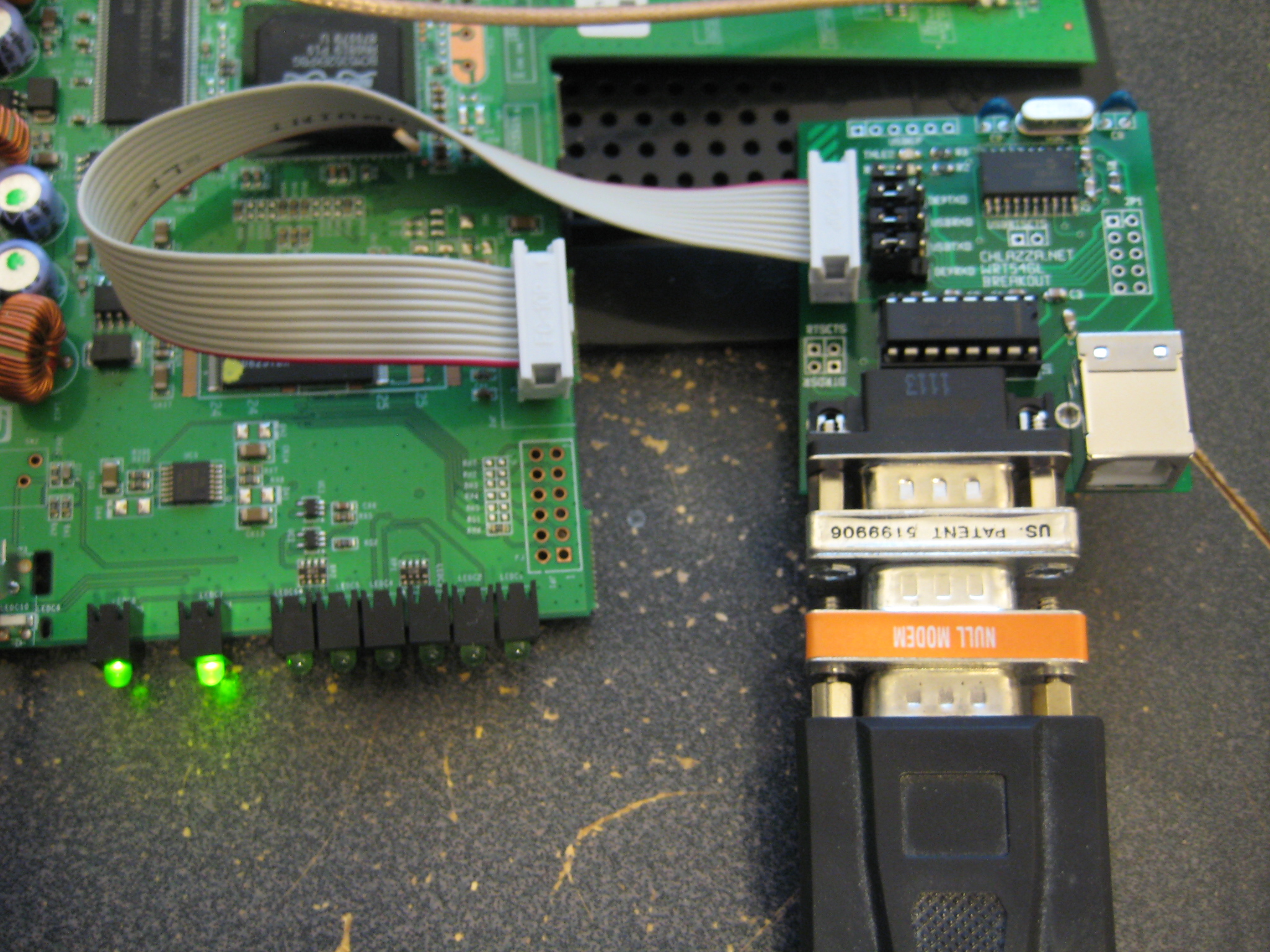
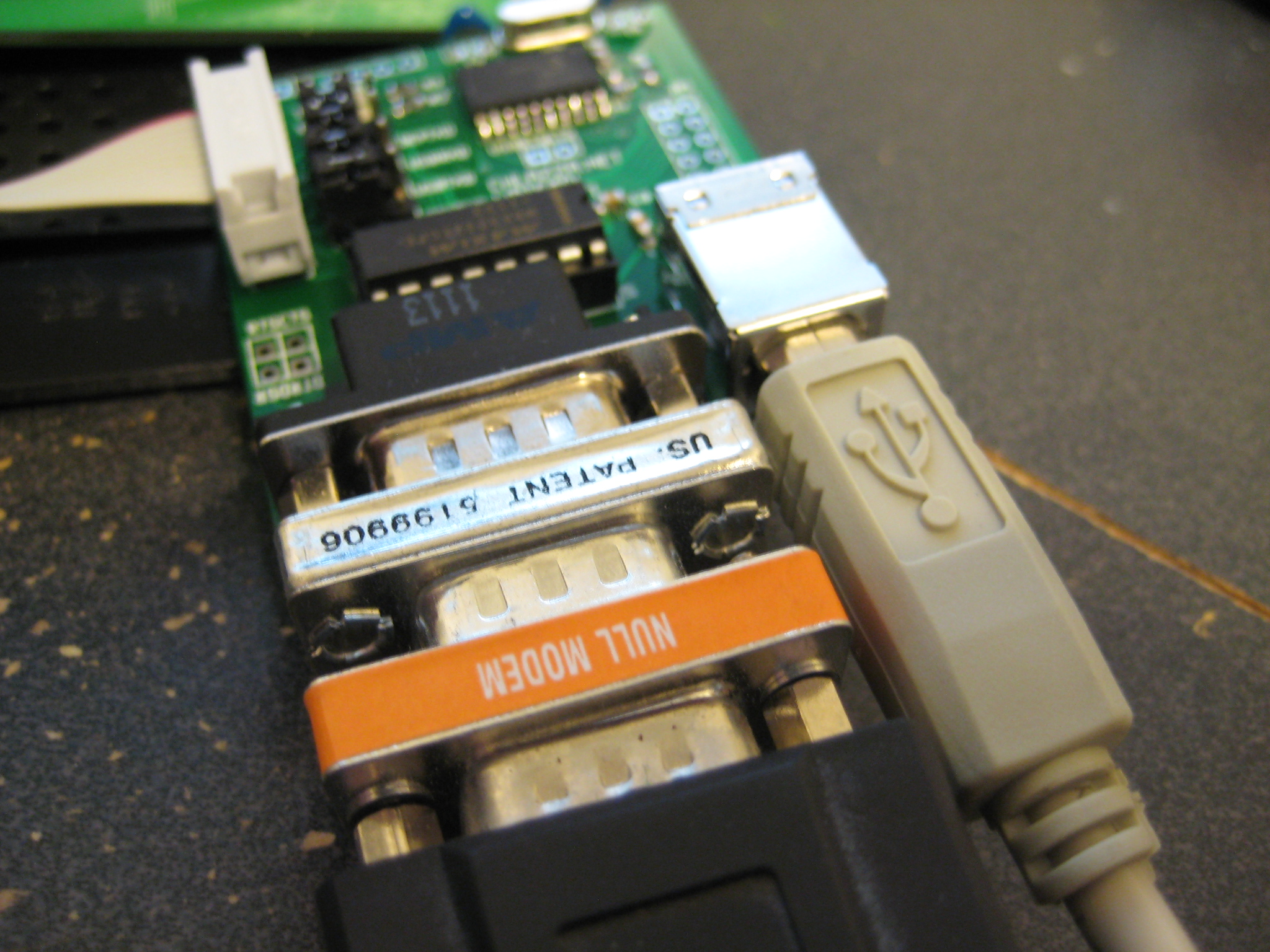
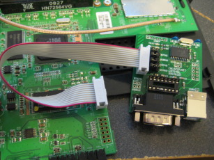
The DE-9 connector I put on the board is male and is wired to be Data Circuit-terminating Equipment (DCE) - i.e. the same socket as found on a computer or dumb terminal. As such connecting the router to a computer requires a null modem and a gender-changer:

On the flip side, attaching Data Terminal Equipment (i.e. your average serial modem) to your router requires no extra equipment, with the possible exception of an extension cable. This is what I imagine most people will use the DE-9 connector for: attaching various peripherals to their router. Practically nobody has serial ports on their computers anymore and thus I expect most people will use USB for configuration, command, and control.
Semi-accidental bonus feature: The Party Line.

Plugging in both serial ports means multiple DCEs can simultaneously manipulate the terminal on the router. Since keystrokes are echoed by the router rather than locally, both sides can see what the other is typing and the terminal session is perfectly mirrored on both connections. Admittedly this is mostly an amusing parlor trick rather than a useful feature, although it may be invaluable for debugging a project that uses a serial device of some kind.
You know, I just realized I didn't actually test the other serial port (S1) through either the USB or DE-9 jack. Oh well.
Other thoughts and further work:
Flip the JPx header footprints on the board.
Numbering pin 1 on the JPx headers in the silkscreen wouldn't be a bad idea.
Some mounting holes wouldn't be missed. Or can I just rely on the DE-9 connector bolts?
Making the MCP2200 USB powered would be nice - wouldn't need to break open a router just to change some settings, would make it possible for the USB serial port to be powered and active before turning the router on (and thus would allow the user to catch all of the start-up text scroll), and may make the board useful for other projects and hacks. Problem is: the WRT54GL requires 3.3 volt signals, while USB provides 5 volts. Adding a regulator isn't some impossible challenge, but more parts means more board space and a higher cost.
DISCLAIMER
All content is owned by its respective creators/licence holders.
Unless otherwise stated, everything else: Copyright © 2009-2011, Chlazza
 Gerber files (back/front copper/mask/silkscreen, outline, drill file) for board: wrt54glbreakout_v2b.zip
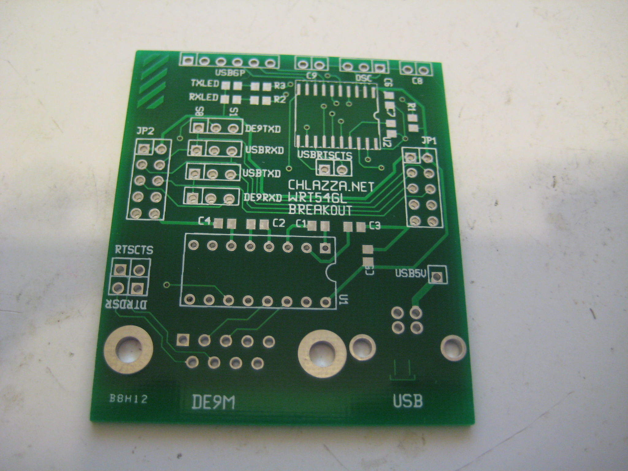

 [2011-10-30]