Passive Infrared Motion Sensor Triggered Infrared Camera Rig
 The property I live on has (among other things) trespassers and apex predators.
You'd think a 'keep out' sign would be sufficient but trespassers have told my landlord to his face that "you can't own land in the mountains!" Sadly, the predators and trespassers rarely meet.
After seeing some suspicious lights in the forest extremely late at night for a couple of days running I decided to see if I could build an motion triggered camera to catch these people in the act. Such things already exists, mainly aimed at the wildlife photography market, but being a niche device they tend to be expensive. Besides, I had recently discovered my Cannon SD750 could take decent photos when only infrared light was available:

I guess they stopped putting infrared filters in their point-and-shoot cameras? (Lighting was provided by an IR floodlight I had built with some cheap IR LEDs and a six cell SLA battery.)
I initially hoped I could trigger the camera with some kind of remote but unfortunately this particular model did not have this feature. I looked into the popular CHDK firmware replacement project - it would let me run a script directly on the camera and it also added an external remote feature. Unfortunately when I run CHDK on my camera the core temp of the processor sky rockets and the battery drains at about one percent every four seconds (not kidding). With enough batteries the power issue was tractable, but the Canon-branded adapter kit (that lets users run their cameras off mains or similar) was upwards of 70USD. Building my own adapter probably isn't impossible but I didn't want to risk damaging a somewhat expensive piece of equipment. The temperature problem really worried me though as I was intended to leave this unattended for days at a time - how hot would the processor get and would that damage the camera? Was there a fire risk?
The solution I settled on was to build a frame that held the camera and positioned two solenoids above the power shutter buttons on the camera. These solenoids would then be driven by a microcontroller circuit that would watch the signal from the motion sensor and control the infrared floodlights. Harder to build, but didn't modify the camera in any way and ensured that the camera wouldn't be powered on for extended periods.
Canon PowerShot SD750
1" wide, 1/8" thick aluminum strip
1/4"-20 thread zinc plated steel threaded rod
Ledex Solenoids, 191172-001 (Code Ident. 81840) (datasheet)
T1-3/4 (5mm) infrared LEDs
Atmel ATTiny25 microcontroller (datasheet, local copy)
TI SN754410 Quadruple Half-H Driver (datasheet, local copy)
Assorted odds and ends.
Schematic for trigger detector/solenoid driver: gEDA gschem format, PNG format
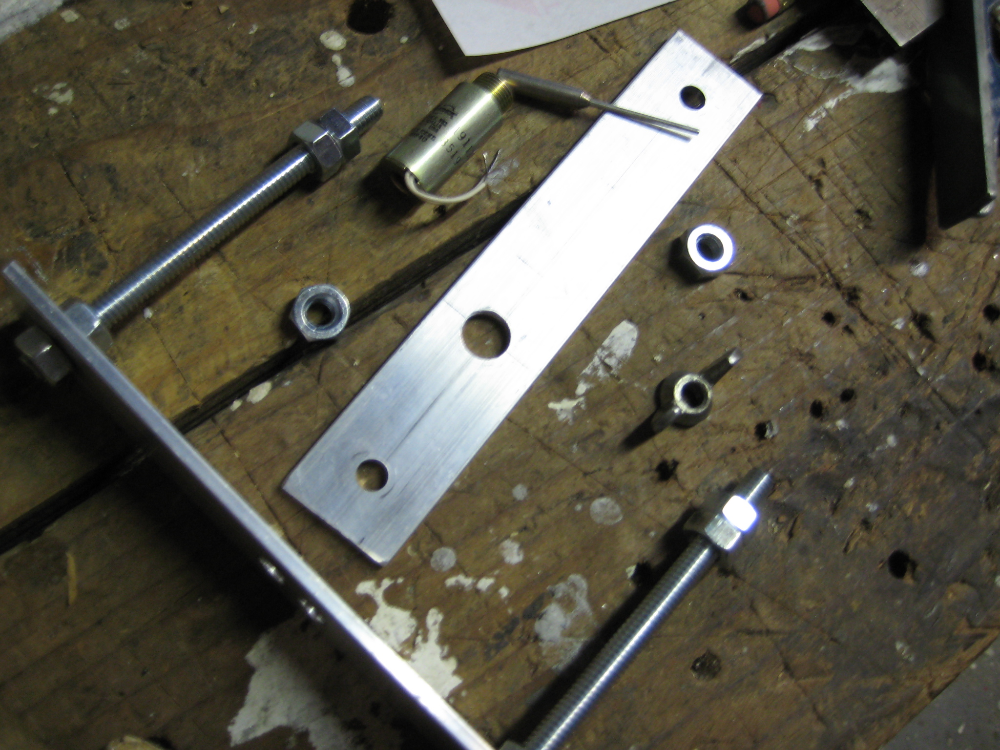
The frame is two metal strips with threaded rod between them, allowing solenoid height adjustment. I was originally using regular nuts but quickly replaced half of them with nylon-insert locknuts - didn't have to worry about losing the height adjustment when removing the camera. The whole rig is held to the tripod by the 1/4-20 screw that threads into the camera.
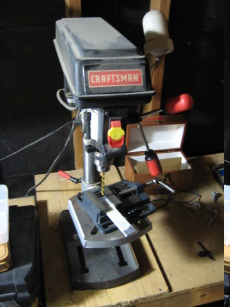

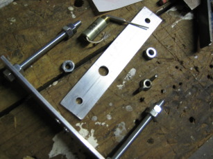
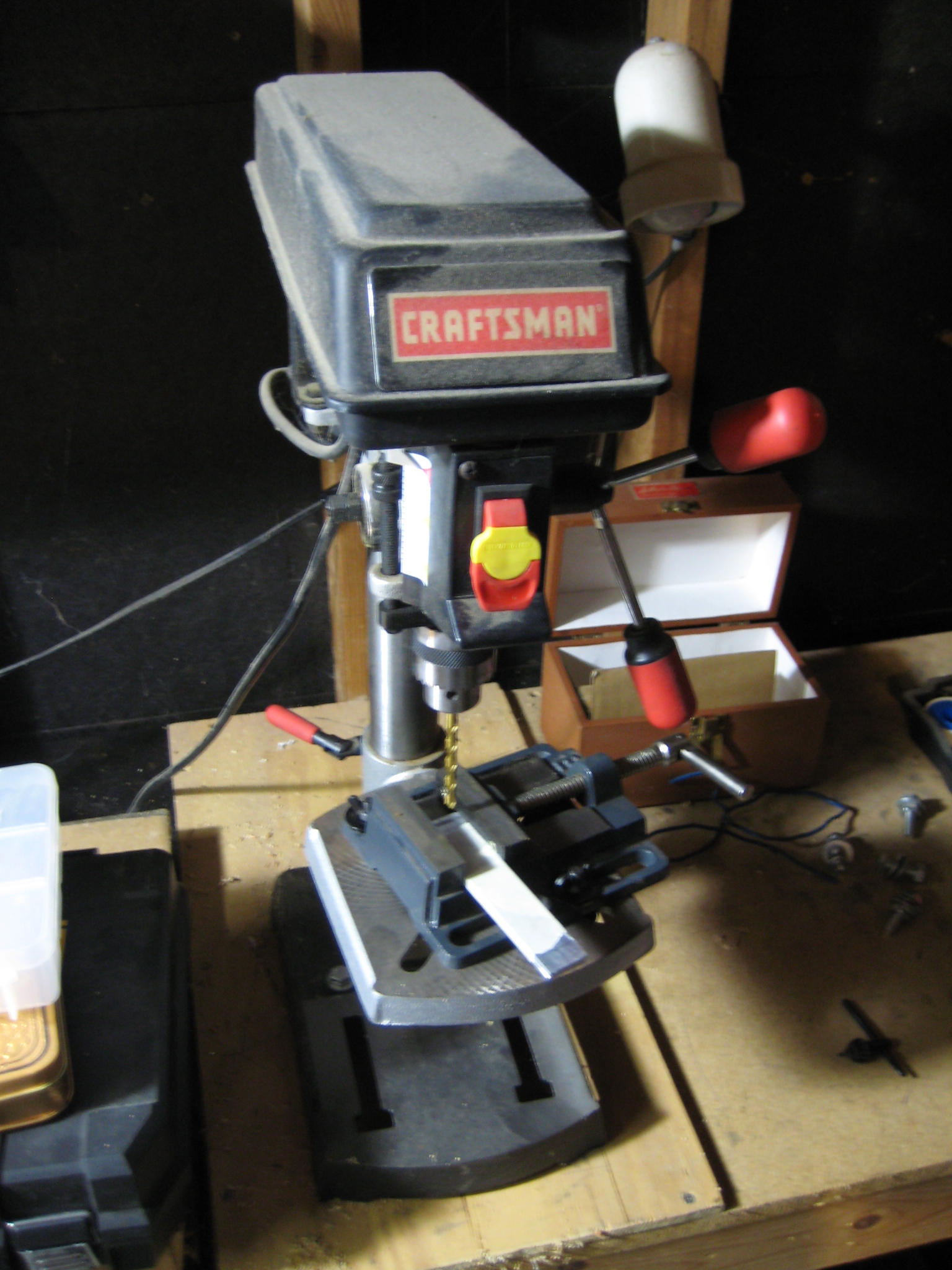
My access to proper machine tools is limited; basically what you see above is all I had, sans a hacksaw, flat file, and a bench vice. As usual the drill bits I needed had wandered off, but I'll never deride a project that gives me an excuse to buy new tools.
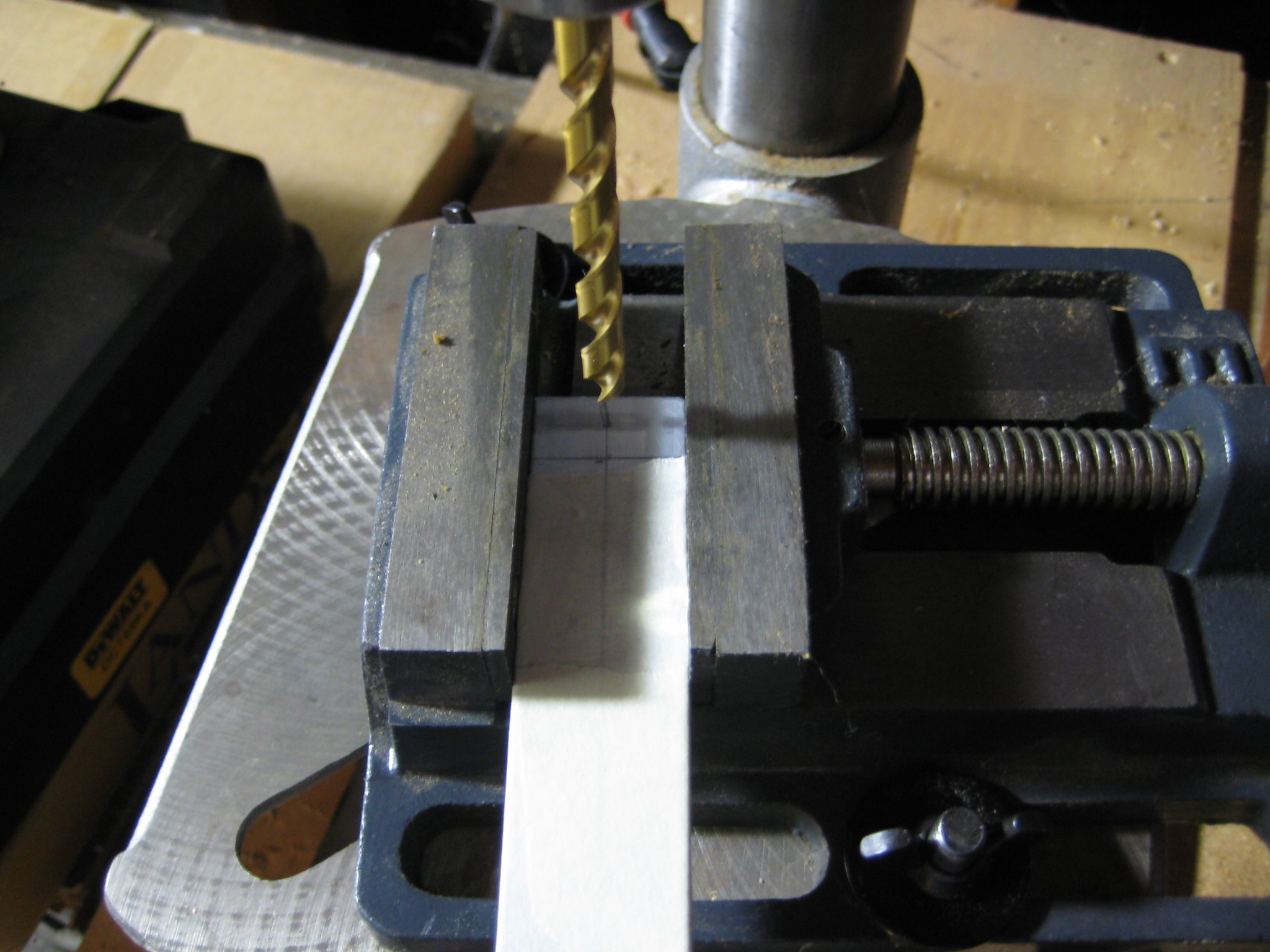
I sawed off a couple length of aluminum strip and tapped them together for the drilling - this ensures that the holes I drilled would line up. I did the best I could with an ancient straight edge/ruler and a pencil to get everything lined up and centered. I just sort of eyeballed the mounting holes for the solenoids and lucked out on the first try - they aren't exactly where I want them, but they are in locations that work.
The solenoids turned out to be interesting. I got them from Allelectronics because they're marked as 12V and expected to run this whole rig off of a car battery. I went Googling for a datasheet and stumbled across the same device for sale from Jameco. Despite both places selling it as a 12V solenoid, the datasheet Jameco provided listed them as 27V (given, not rated for continuous duty). Well, whatever, they seem to work at 12V just fine.
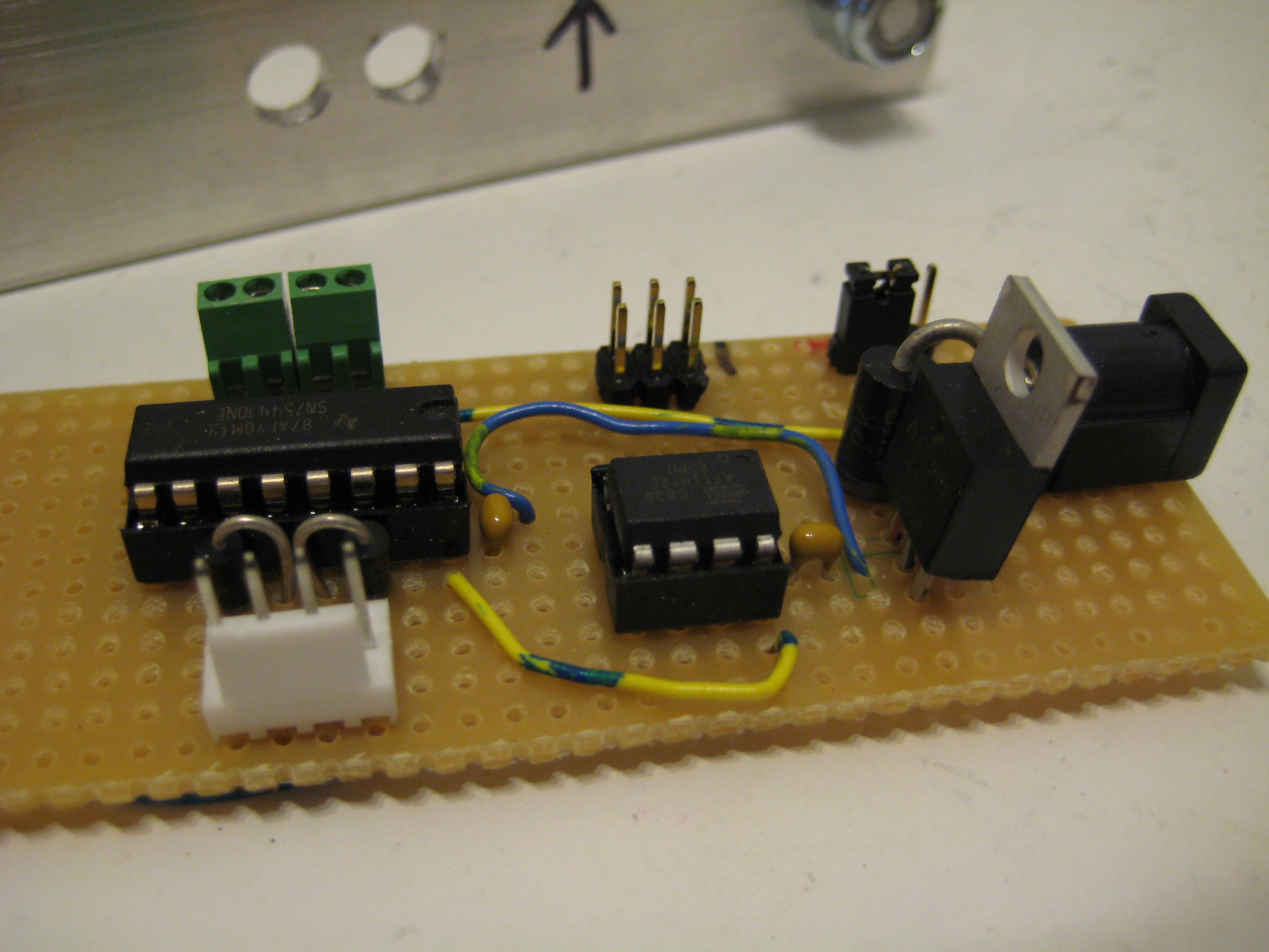
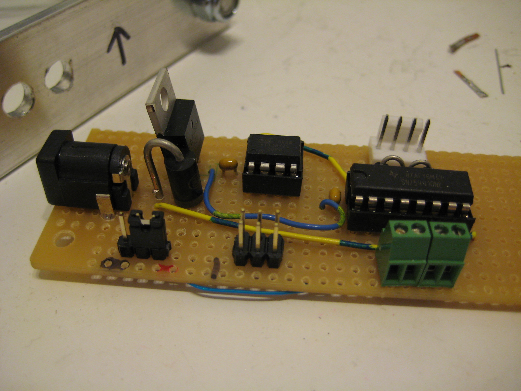
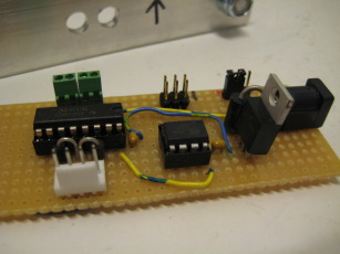
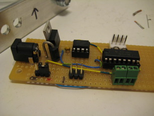
Nothing special here; just an ATtiny25 and an SN754410 H-Bridge. The green screw terminals are for lighting and other non-inductive lads. The white header connects to the solenoids. I don't think I have the trigger pin broken out in this image. See the schematic (above) for further details.
The trigger detector/driver board is programmable so it can accept pretty much any input signal. A passive infrared sensor seemed like a good choice - doesn't need a lot of setup (no need to dig holes for electronics, run wires, or rig up reflectors), and is used in some common systems (alarm systems and light switches mostly) and thus should be easy to find.
In my case, I had access to the detritus from a recently built house. By sheer chance, this happened to include a bag of about five unopened PIR light switches. I figured they would be pretty simple - a power supply to drop mains voltage down to something the sensor could handle, the sensor system itself, and some kind of high-current semiconductor switch.
By sheer chance I was mostly right.


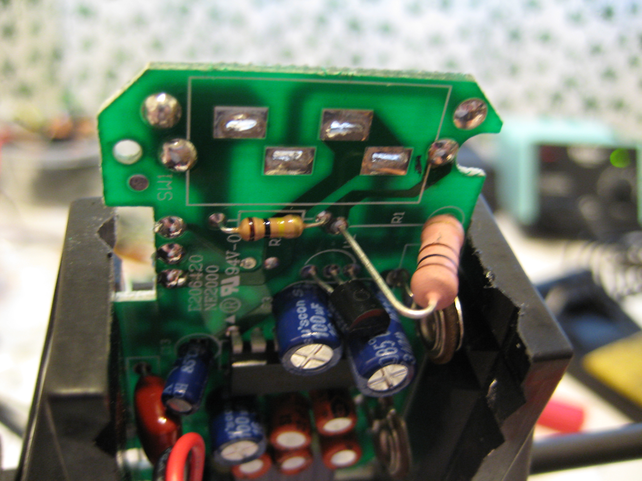
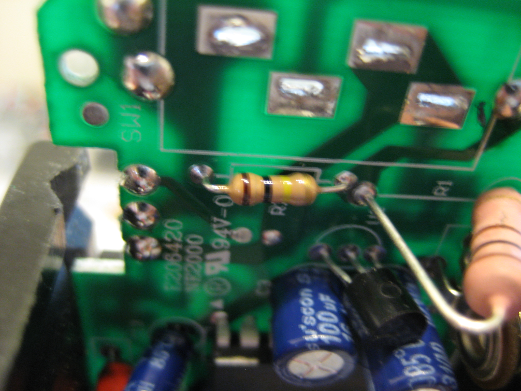
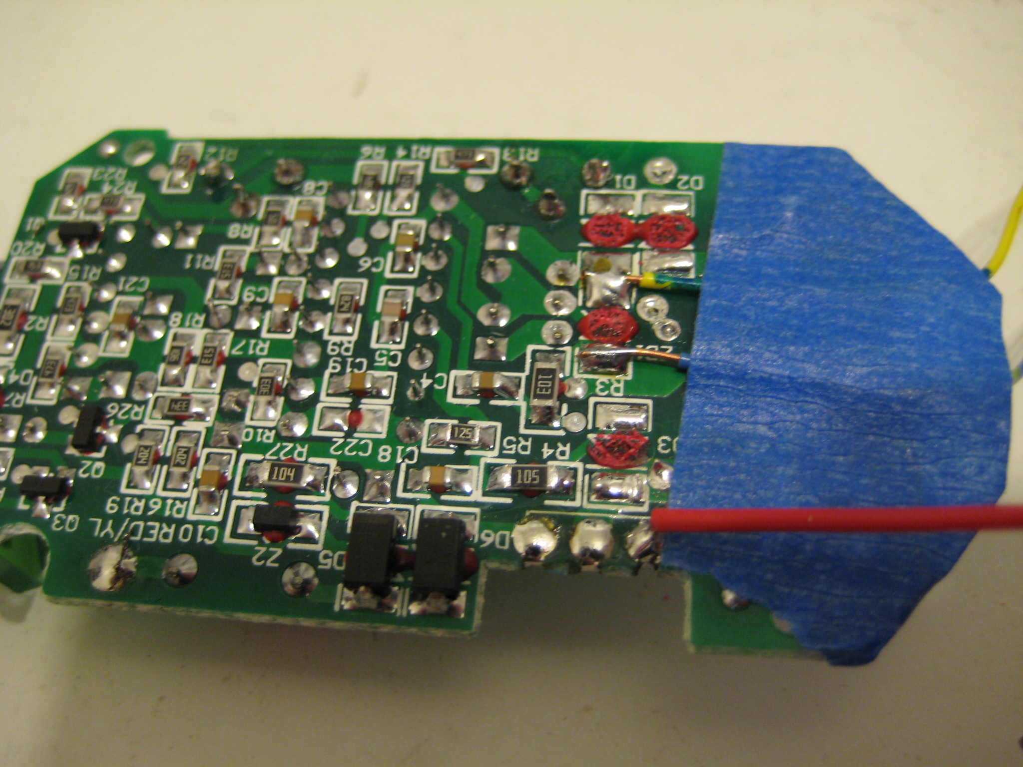
At this point I've removed the main power switch. That huge resistor on the right is actually in series with the linear regulator just below it - basically dropping the voltage from mains to something the LR could handle. The other resistor was for pull-down, if memory serves.

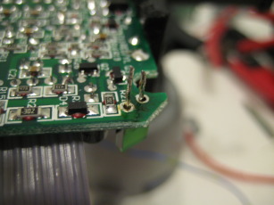
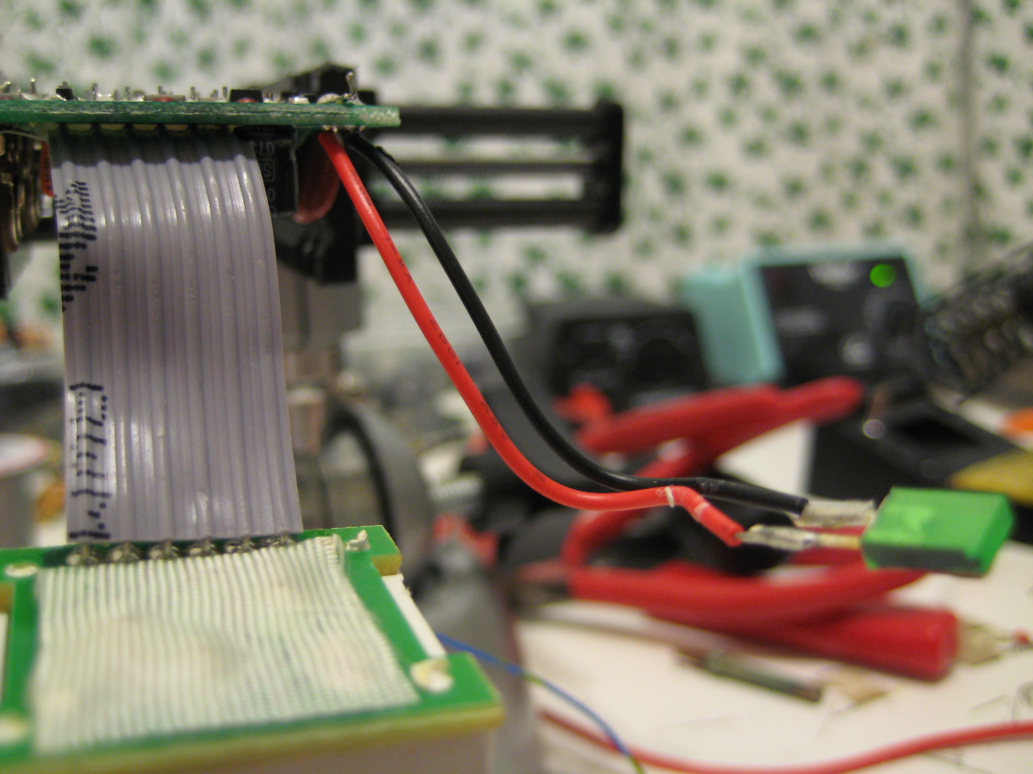
Repositioning the status LED. That thing in the low left of the photo (on the end of the gray ribbon cable) is the PIR sensor, currently facing down.
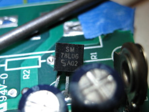
78L06 you say? Checking the voltage confirms that it's putting out 6 volts. Googling the part number shows ~100mA 6 volt linear regulators in a TO-92 package.
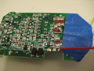
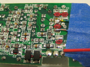
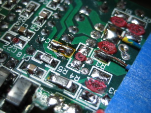
See those red spots? Those are blobs of glue that were holding rectifier diodes on. I also pulled off and bridged what appears to be a filter capacitor (C4). The wires running under the blue tape are ad-hoc power leads. The red wire is connected to where the high current solid-state switch was. In theory, when the PIR module triggers, that line should go high.
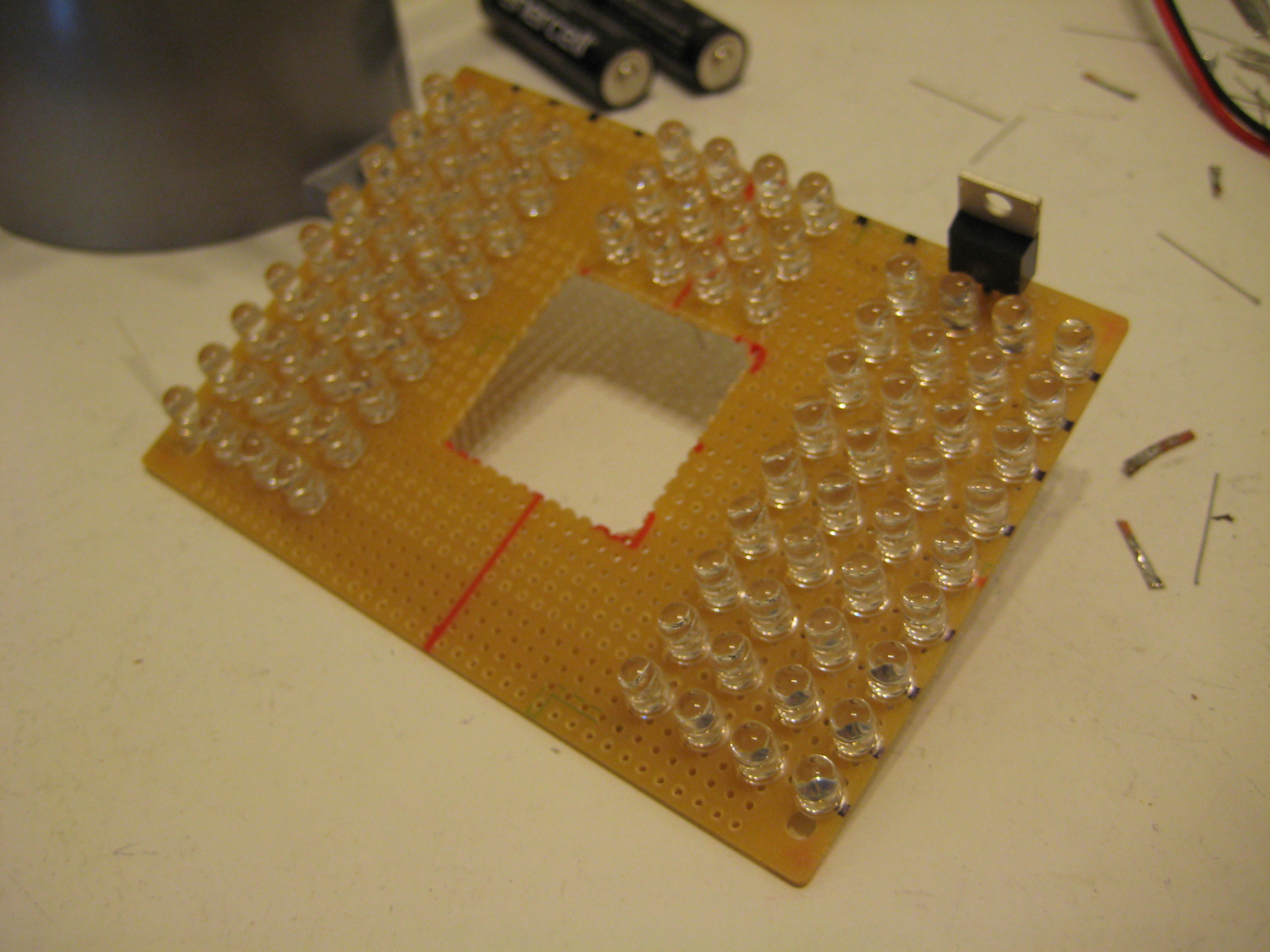
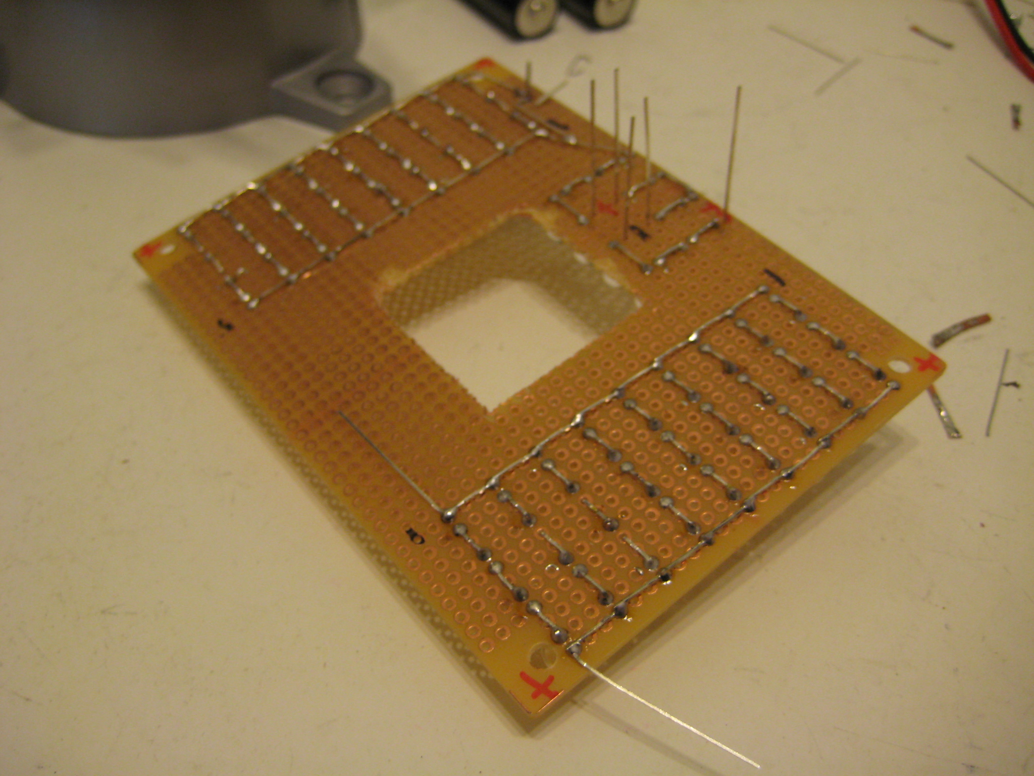
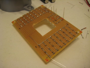
I actually mucked this up. The camera lens assembly is off center so when mounting the camera in the frame the lens is actually off to the right from the centerline. I punched the hole in the middle of the board without thinking about it too hard. All is not lost due to the magic of zipties and duct-tape, but still.
Note the lack of load resistors. That TO-220 is a 5 volt regulator - I just tie four LEDs in series and underdrive it with five volts (IR LEDs have a forward voltage of 1.5 volts, times four is 6 volts). Some electrical engineer somewhere is probably facepalming somewhere right now because of that.

DISCLAIMER
All content is owned by its respective creators/licence holders.
Unless otherwise stated, everything else: Copyright © 2009-2010, Chlazza