MAX1811 Lithium Ion Cell Charger Demonstration Board
 The concept of charging a Lithium Ion cell is a fairly straight forward (see the details on my battery page) but is complex enough (and the failure mode dangerous enough) that 'dumb' chargers are a bad idea. Consequently there are a fair amount of dedicated battery charger ICs available from the usual suppliers. I've been using the MAX1555 for a while, after I saw them available at SparkFun, but their size (TSOT/5 package) doesn't lend them to hand soldering. Recently I came across the MAX1811 which fills a similar role as the MAX1555 but has some interesting additional features: selectable battery voltage (4.1V and 4.2V), selectable charge current (100mA, 500mA), and comes in a much easier to solder SOIC (narrow) 8-pin package.
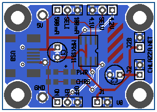
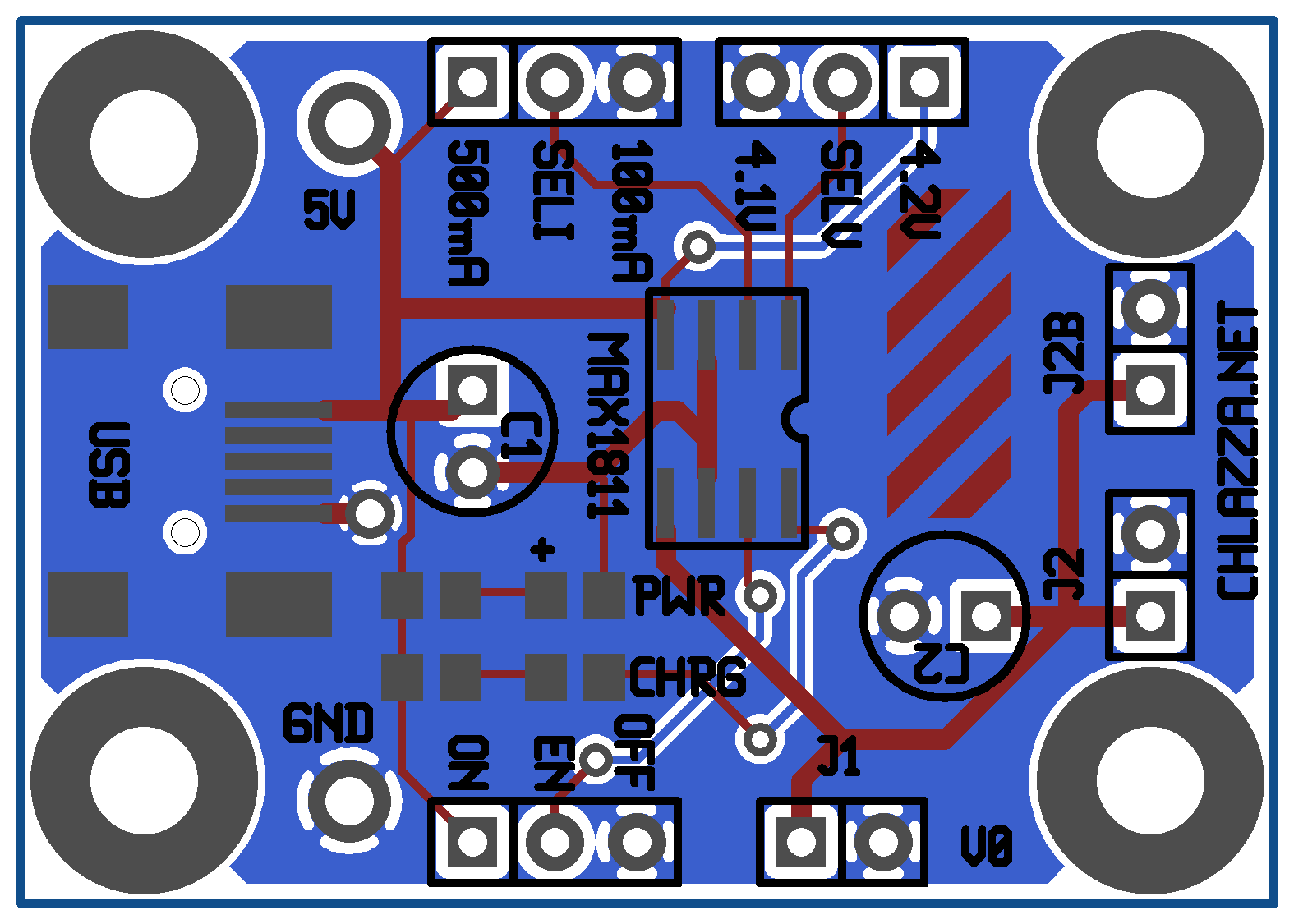
I designed the board with the intention of using what I had on hand for parts - if this was a professional product intended for mass production the caps would be replaced with surface mount parts and I probably would have put more thought into the mounting holes. Capacitor C2 is placed in a such a way that the user can 'lay down' a larger cap on the board if needed. Useful if the user is driving noisy loads off of the battery and need to put some filtering on the net, but doesn't want jury rig some free hanging caps. Also makes a neat space for the logo. The USB mini-B jack is a bit of an experiment; I have a stack of them sitting around and a footprint I never used from when I was designing those little matrix displays, and it's a good source of regulated 5 volts. Bonus: cheap wall warts that terminate in mini-B (originally intended for cell phones and other small devices) are widely available and USB ports are ubiquitous on modern computers (just make sure to drop the charge current to 100mA). In case I want to use the board with a different power supply or I want to pull some USB power for some reason there are large plated holes on the five volt and ground nets. Footprints J1, J2, and J2B are all outputs. J1 is placed and spaced for some screw terminals I have. There are multiple outputs so the user can attach a battery to one and then wire whatever to the others and thus won't need to disconnect anything to charge the battery.
As an aside, I'm intrigued by how USB ports are increasingly being regarded as convenient power jacks in addition to data connections. That fact that one can buy power bricks that only have USB sockets on them is amusing to me.
 Gerber files (back/front copper/mask/silkscreen, outline, drill file) for board: max1811demo_v0.zip
Layout (gEDA PCB format): max1811demo_v0.pcb
Schematic: gEDA gschem Format / Encapsulated Postscript / PNG
Maxim IC MAX1811 Lithium Ion Cell Charger IC (datasheet, local copy)
[2011-11-02]
Boards ordered!
[2011-11-28]
Check it out:
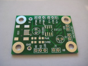
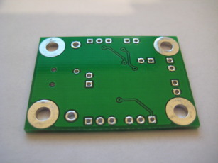
I like BatchPCB; reasonable prices, and they tend to send along extras. In this case I ordered two boards and they sent me four. As I understand it: they include multiple copies of each design into each panel run so if one iteration comes back missing traces or what-have-you, they still (probably) have a product to send along to the client. And if they have extras they send them along as well.
Fine by me.
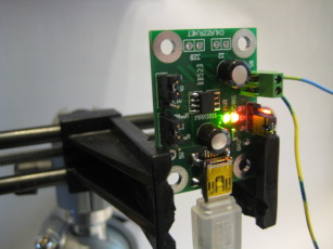
Putting it together was easy, with the exception of the miniB USB jack (as expected): those pins are tiny and are partially obstructed by the jack. Thankfully the power and ground pins are on the 'outside' of the footprint, so I could sneak the iron tip in there without much trouble. I left all the other pins unconnected. In future buildups I may trim them off to avoid solder shorts.
I'm testing the board as we speak, using a LiPoly cell salvaged from a MacBook Pro battery as a test subject. I can't get the chip to run at 500mA charge rate; I set the jumper and plug it in, but the charge indicator doesn't illuminate. Works fine at 100mA however; I'm wondering if the power adapter I have the board plugged into (some cheap no-name brand wall wart with a USB jack) can't provide 500mA.
DISCLAIMER
All content is owned by its respective creators/licence holders.
Unless otherwise stated, everything else: Copyright © 2009-2011, Chlazza
 Gerber files (back/front copper/mask/silkscreen, outline, drill file) for board: max1811demo_v0.zip

