ATMega48 Driven LED Matrix Display
 The initial project was to build a web-enabled sign with a 16x2 character display and with each character being a 6x7 matrix of discrete LEDs. (Based on the NextBus sign system in San Francisco.) Doing the math, that works out to a 1344 pixel display. I dislike flickering displays so when I initially looked into this project I looked for ways to drive all the LEDs individually. This is fairly straight forward, but the part count exploded and thus ran counter to my 'keep it simple as possible' directive. It also turns out that on a per-LED basis (from Futurlec at least) LED matrix displays were cheaper than discrete LED (about 0.03USD per pixel versus 0.06USD per LED, respectively). Unfortunately the LED matrix displays that Futurlec stocks (and most LED matrix displays in general I assume) use system where each row or column of the display has a common anode or common cathode - for example, on the displays I used, each row of LEDs had a common anode and each column had a common cathode. One can light up more than one LED at a time but they are restricted by the aforementioned row/column bus arrangement - lights can't be flipped on arbitrarily. It would be far easier to illuminate one LED at a time and cycle through each LED on the display rapidly, briefly illuminating each as needed.
Something that is often overlooked about many of the Atmel ATMega line of microcontrollers (and I presume other microcontrollers of other makes and models - YMMV) is that the digital I/O pins are able to both source and sink around 20mA (I think?) of current. This makes driving an LED matrix display exceptionally easy - no need for sink transistors or similar, just run the cathode buses into the microcontroller. In the case of the ATMegaXX8 series, one of these controllers has enough pins to drive a display with ease and have pins left over. I have an affinity for I2C/TWI buses and in this case it was perfect: add some way to address each module and one can control a whole mess of displays with two wires.
I noticed that Futurlec was selling 8x8 displays for about 3USD each - pretty good compared to other suppliers. Futurlec also had SMD ATMega48's (the version of the ATMegaXX8 series with 4k flash) for about 2USD each. I picked up a couple of those along with the displays and added some 0805 SMD capacitors and resistors on my next Digikey order. Parts on the way, I set to work designing the board.
Parts
Atmel ATMega48 microcontroller (datasheet, local copy)
Ningbo Flying Electronics Co., Ltd. NFM-12881xx 8x8 LED matrix display (datasheet)
Taiwan Oasis TOM-1088BMR-B 8x8 LED matrix display (datasheet)
0.1uF 0805 capacitor
270 ohm 0805 resistors
Files
Schematic: gEDA gschem format, PNG format
AVR programming header symbol: 6-pin
ATMegaXX8 TQFP gschem symbol: atmeg48_88_168_328_tqfp.sym
NFM-12881xx gschem symbol: NFM-12881xxx.sym
TOM-1088BMR-B gEDA PCB footprint: TOM-1088Bx.fp
Software: matrixdisplay.c
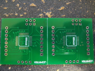
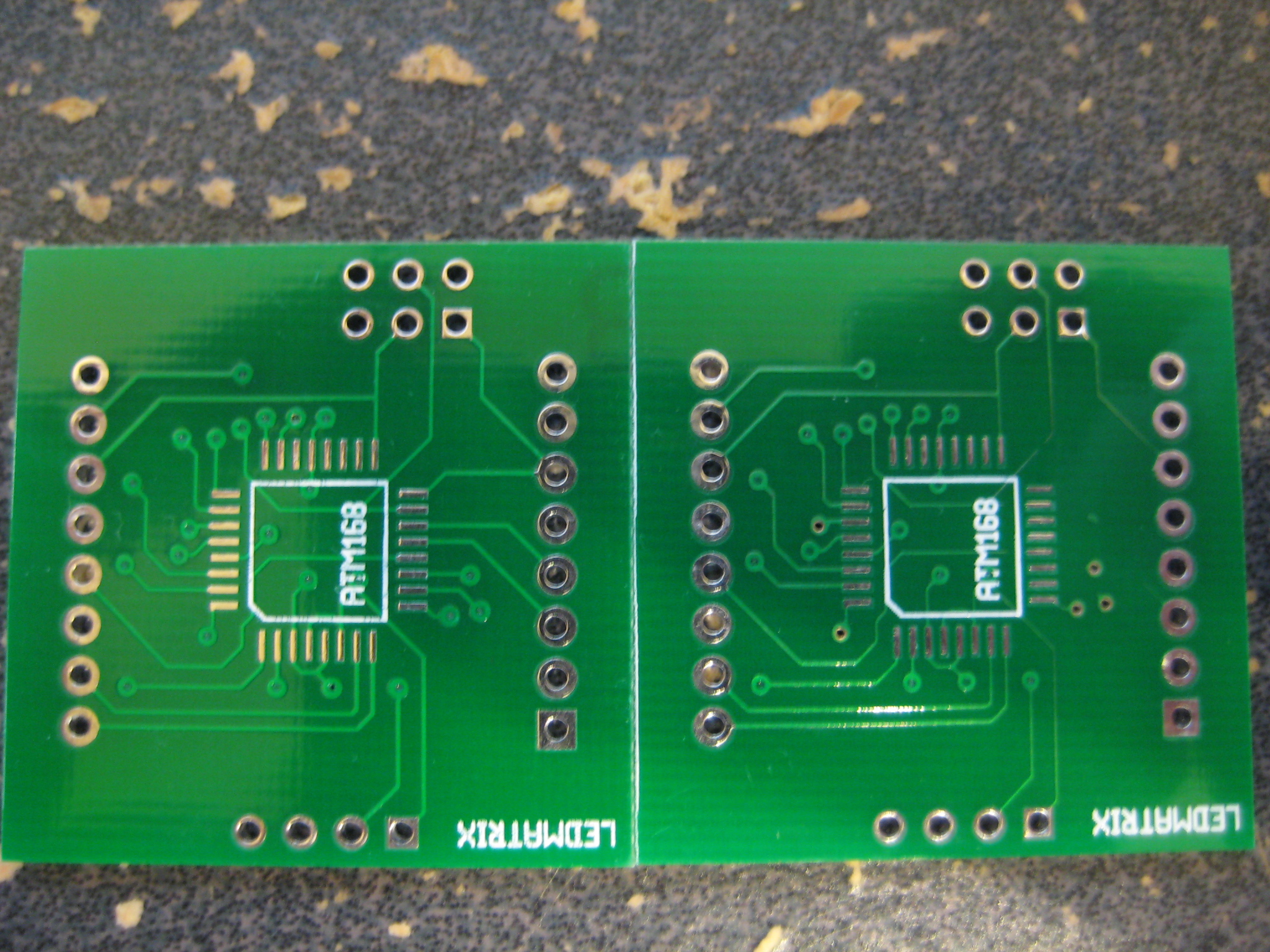
I ordered the boards through BatchPCB. Technically I only ordered one, but they do a double batch of each mass order and often they'll send along the spare as well at no charge. This time the extra came with some of the traces missing - a first for BatchPCB in my experience. Oh well - I still have a functional board.
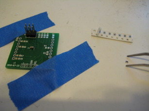
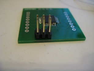
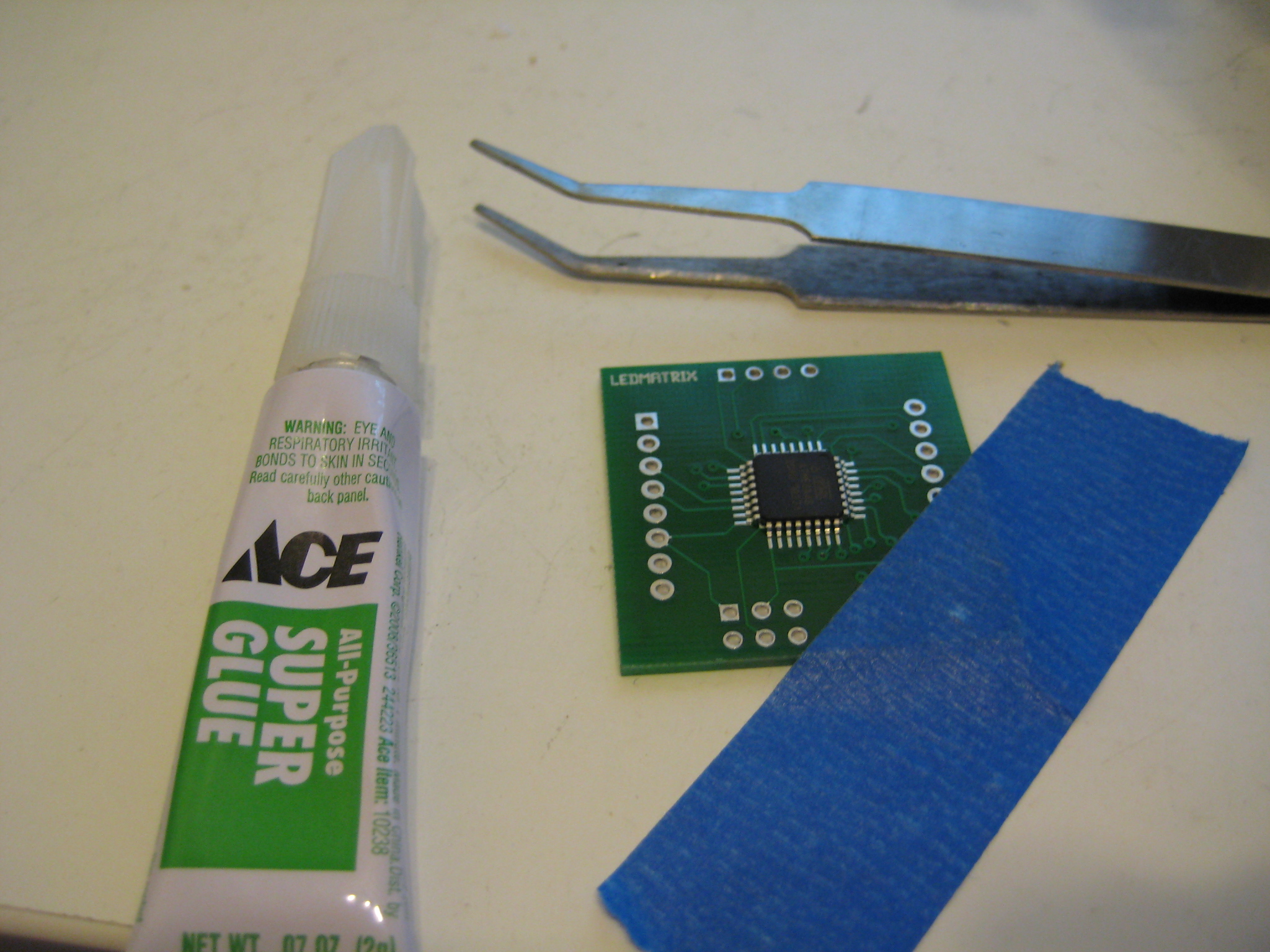
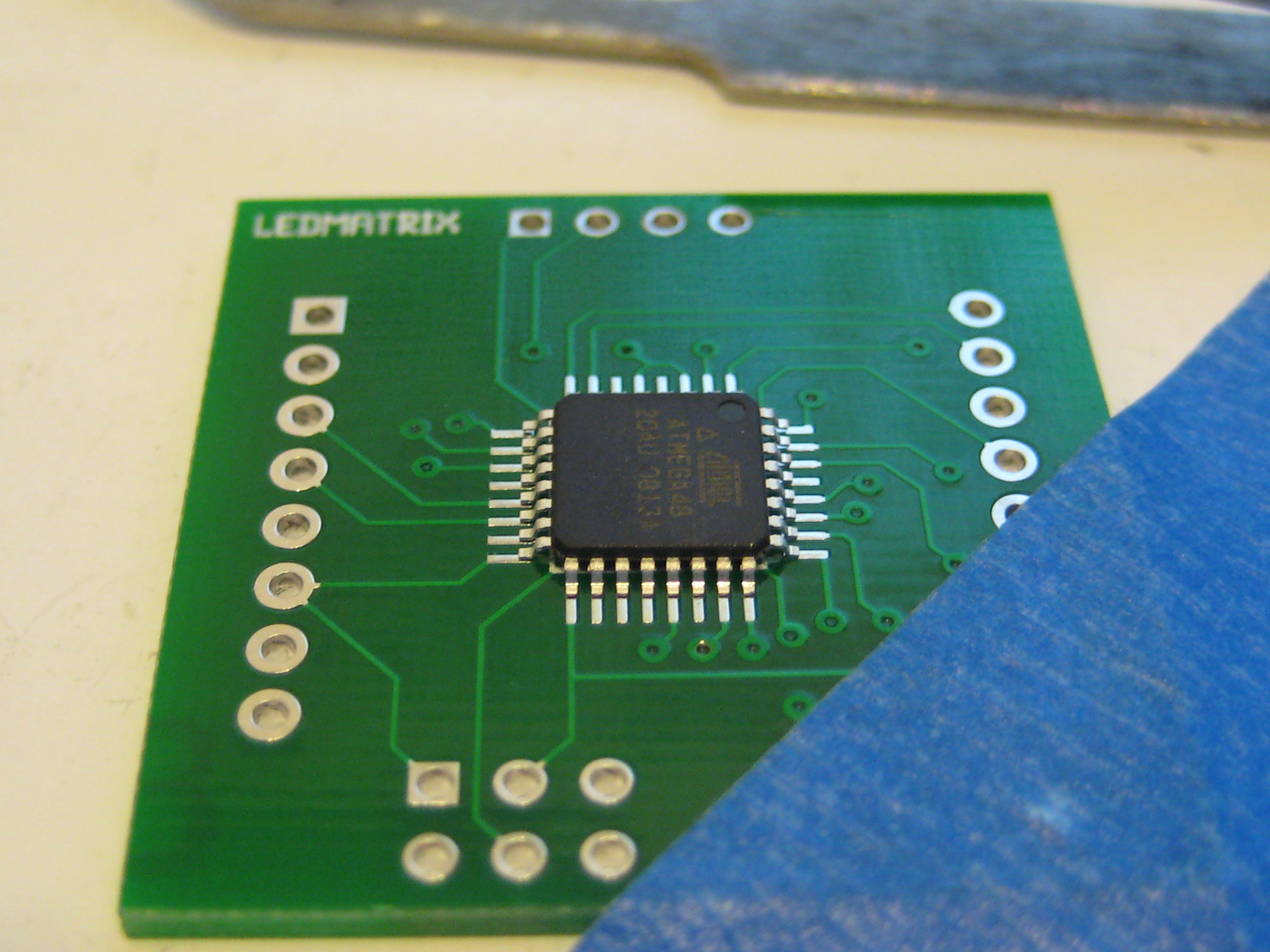
The ATMega48 was easier to solder down than I expected. Gluing it down first makes it a hell of a lot easier to work with and a lot harder to rip a pad off - just make sure the glue is dry before you do anything. I tried to only solder down one pin at a time, but I usually wound up blobbing solder over a bunch of them. A steady hand and some solder wick are very useful here.


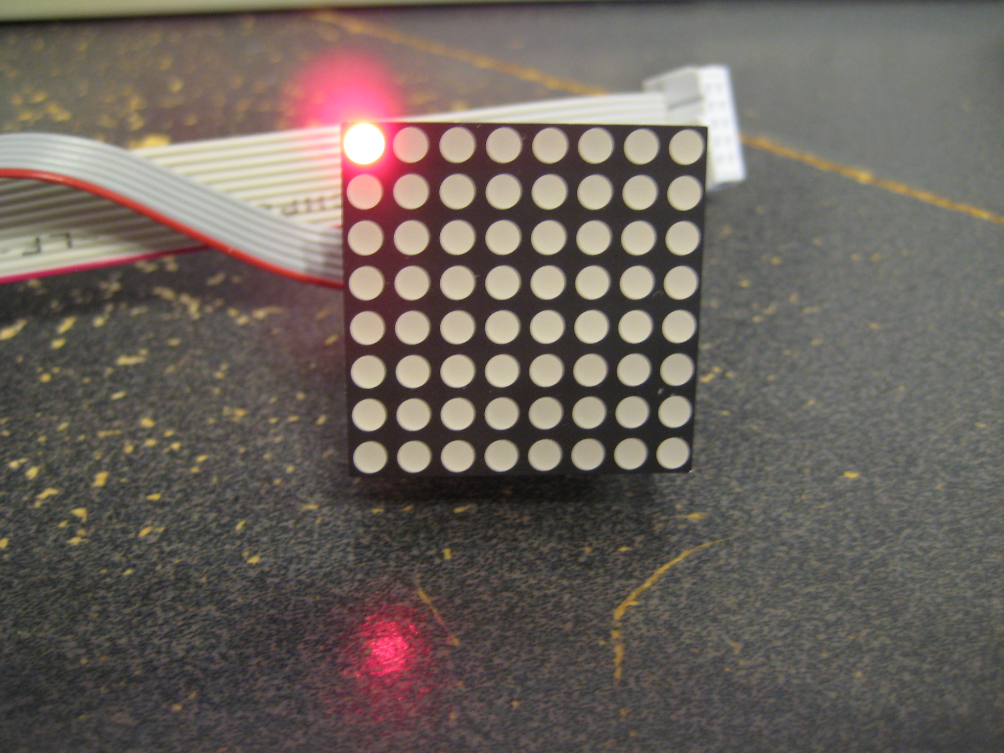
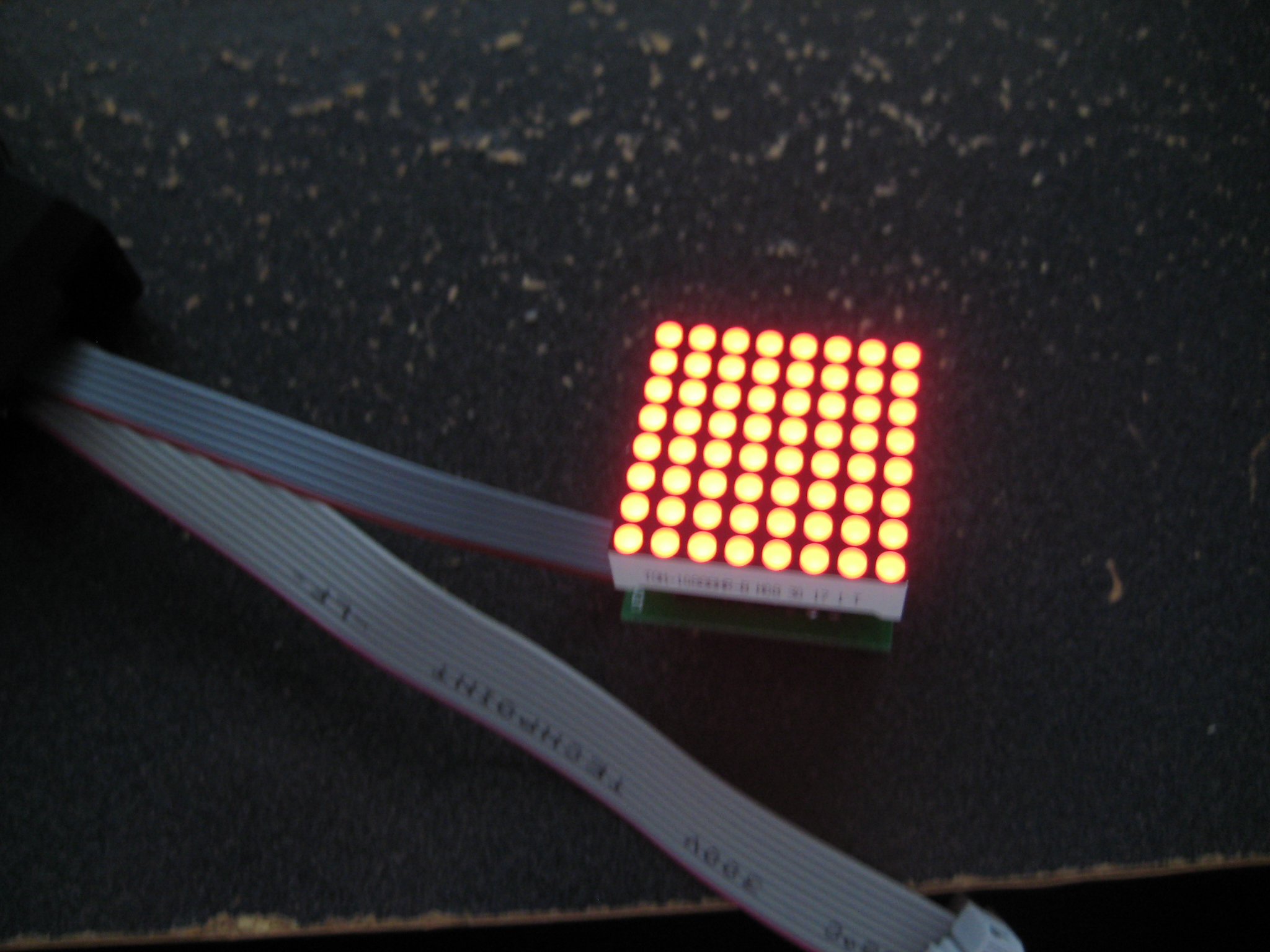
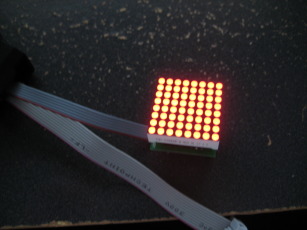
There are eight current limiting resistors but these are mostly for testing purposes. These let me drive a single LED contentiously without damaging it. In the 'production' code I iterate through all the LEDs in the matrix several times a second, briefly turning each on as needed. In that case I'm told the resistors aren't strictly required as the LED won't be on long enough to be damaged. All in all it doesn't hurt to have them.
 Initially I made plans around the Ningbo Flying Electronics Co., Ltd. (yes, that is apparently their real name) NFM-12881xx series of LED matrices. I figured that was what Futurlec would ship me, based on the part number in the picture on the details page for that part. I thought it odd that they didn't have an exact part number clearly listed on the info page, however - just a brief rundown of the electrical specs. When the box of parts arrived I was somewhat surprised to find they had shipped me Taiwan Oasis TOM-1088BMR-B displays instead. I dug up a datasheet and confirmed that the pinout was the same, but electrical specs were slightly different (the Oasis part had a recommended current of 12mA compared to 20mA for the Ningbo part). Not a big deal (this isn't going into space) but I'd still like to know what I'm buying before it arrives in my mailbox.
You may note number of 'switches' in the schematic on pins 23 through 26. These are intended as address pins - if a number of displays are connected on an I2C bus for example, these solder pads can be shorted to give each device a unique identifier. This lets the user dump the same code onto each device and allows for easy visual identification. These pads also serve are breakout points for these pins so the user can extend the functionality of the board (note that an alternate function of the pins is ADC input).
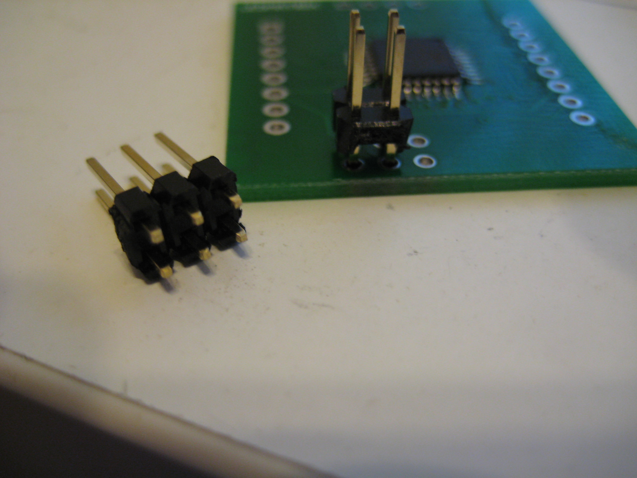
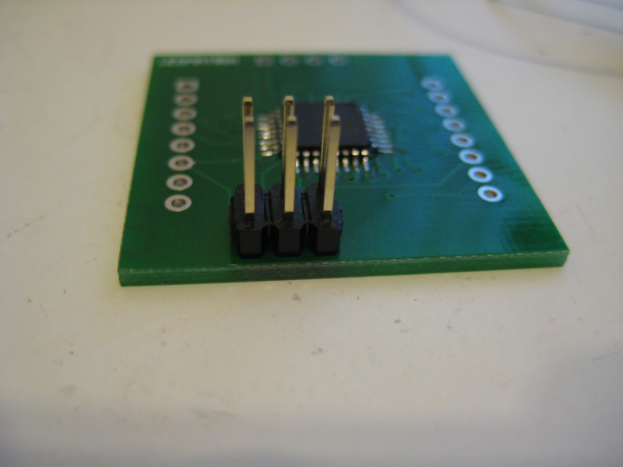
There is a standard six pin AVR programming header on board. I was careful to make sure the MOSI, MISO, and SCK lines were on pins that were intended to sink the display pins. That way we don't have these nets shorting to other pins on the '48 and preventing in-circuit programmers from accessing the chip successfully. I didn't think it would cause a problem - I don't think the other pins on microcontroller's pins are grounded when its being programed and I don't think the states matter - but I'd rather head off potential problems before they become an issue (particularly since the '48 is trapped under the permanently attached display). For all the headers I used a table surface and a screwdriver to push the plastic retaining thingy down the pins so the end of them was flush with the display side of the board.
Initially I made plans around the Ningbo Flying Electronics Co., Ltd. (yes, that is apparently their real name) NFM-12881xx series of LED matrices. I figured that was what Futurlec would ship me, based on the part number in the picture on the details page for that part. I thought it odd that they didn't have an exact part number clearly listed on the info page, however - just a brief rundown of the electrical specs. When the box of parts arrived I was somewhat surprised to find they had shipped me Taiwan Oasis TOM-1088BMR-B displays instead. I dug up a datasheet and confirmed that the pinout was the same, but electrical specs were slightly different (the Oasis part had a recommended current of 12mA compared to 20mA for the Ningbo part). Not a big deal (this isn't going into space) but I'd still like to know what I'm buying before it arrives in my mailbox.
You may note number of 'switches' in the schematic on pins 23 through 26. These are intended as address pins - if a number of displays are connected on an I2C bus for example, these solder pads can be shorted to give each device a unique identifier. This lets the user dump the same code onto each device and allows for easy visual identification. These pads also serve are breakout points for these pins so the user can extend the functionality of the board (note that an alternate function of the pins is ADC input).
There is a standard six pin AVR programming header on board. I was careful to make sure the MOSI, MISO, and SCK lines were on pins that were intended to sink the display pins. That way we don't have these nets shorting to other pins on the '48 and preventing in-circuit programmers from accessing the chip successfully. I didn't think it would cause a problem - I don't think the other pins on microcontroller's pins are grounded when its being programed and I don't think the states matter - but I'd rather head off potential problems before they become an issue (particularly since the '48 is trapped under the permanently attached display). For all the headers I used a table surface and a screwdriver to push the plastic retaining thingy down the pins so the end of them was flush with the display side of the board.

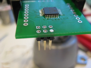
I intended for these displays to be used with an I2C bus. The ATMegaxx8 series has built in hardware to handle I2C-compliant buses so I broke those pins out with a power and ground pin to a 0.1" spaced four pin header. Fun fact: the programming header, I2C bus header, and display pins are all placed on the same 0.1" grid. In theory it should be possible to drop a piece of perf board on the bottom of this thing and have all the pins line up with the predrilled holes.
And that is pretty much it. The whole thing is twelve parts, not counting headers. Four if you drop the resistors, and you don't absolutely need the bypass cap either.
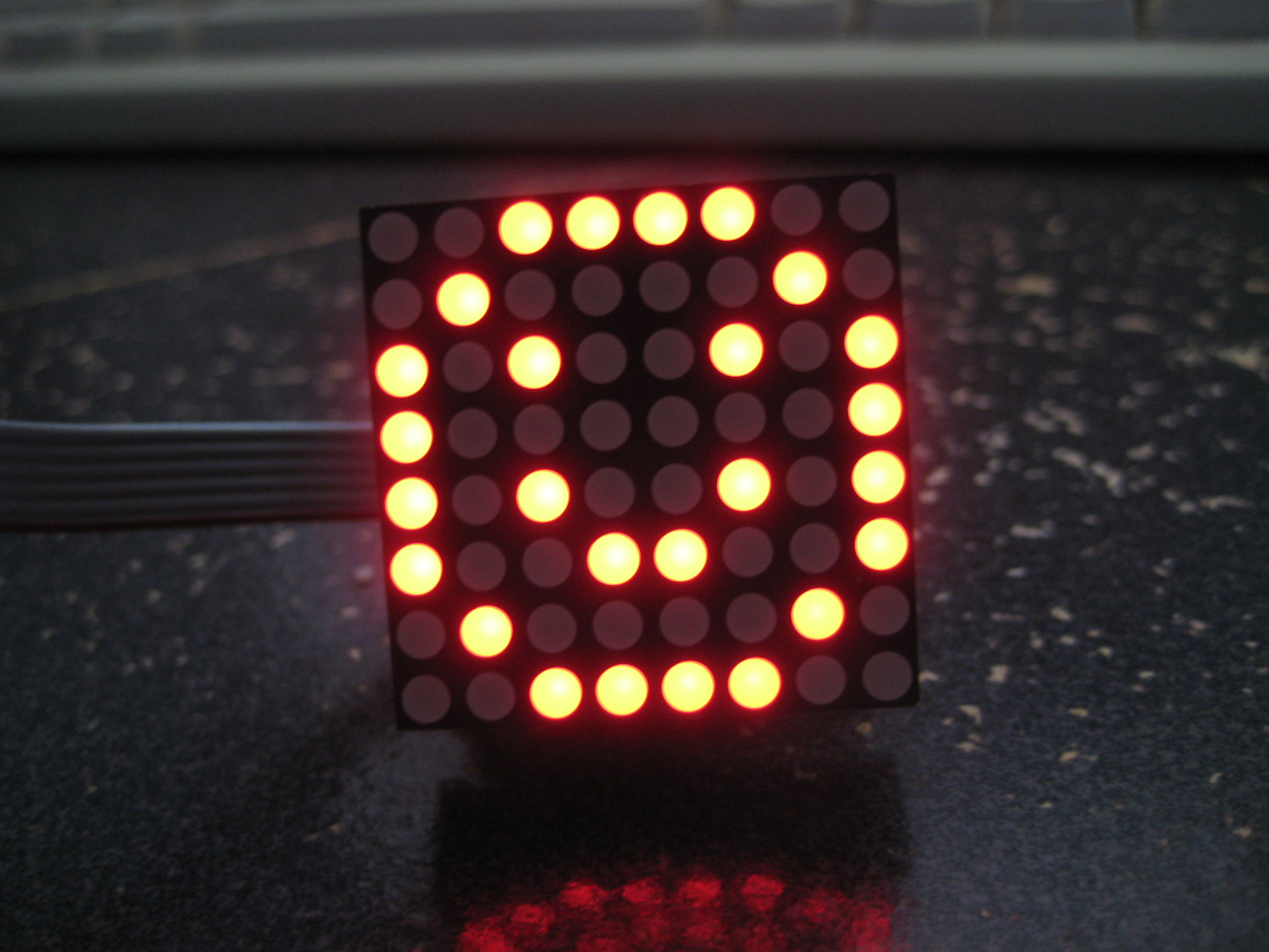
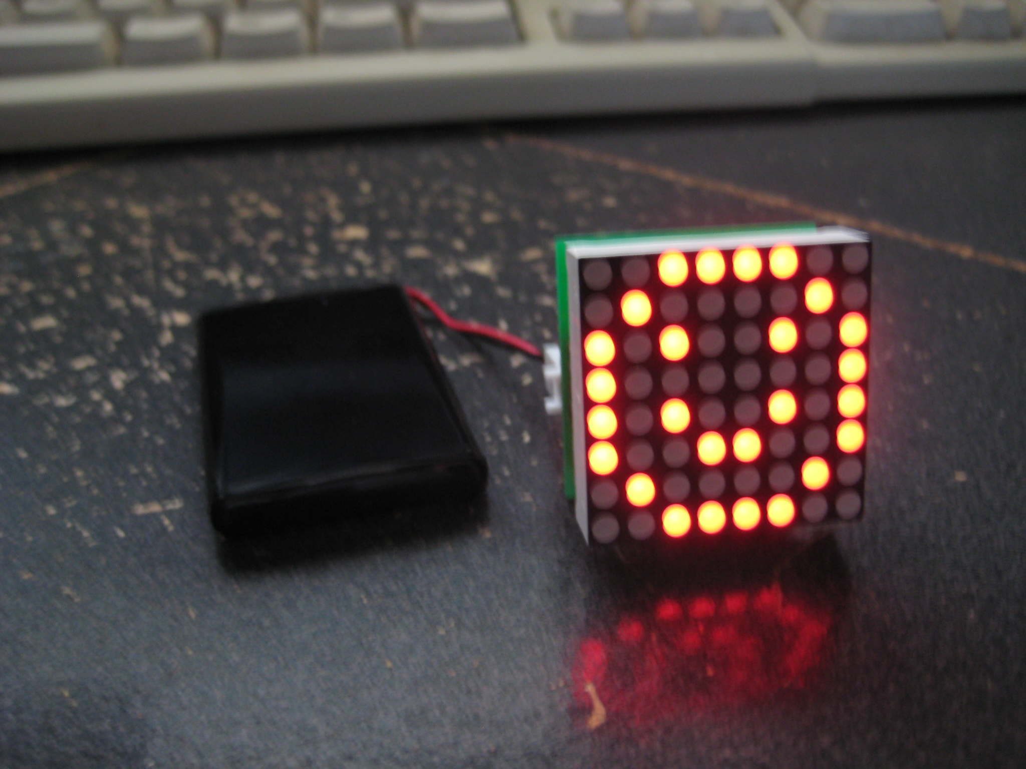
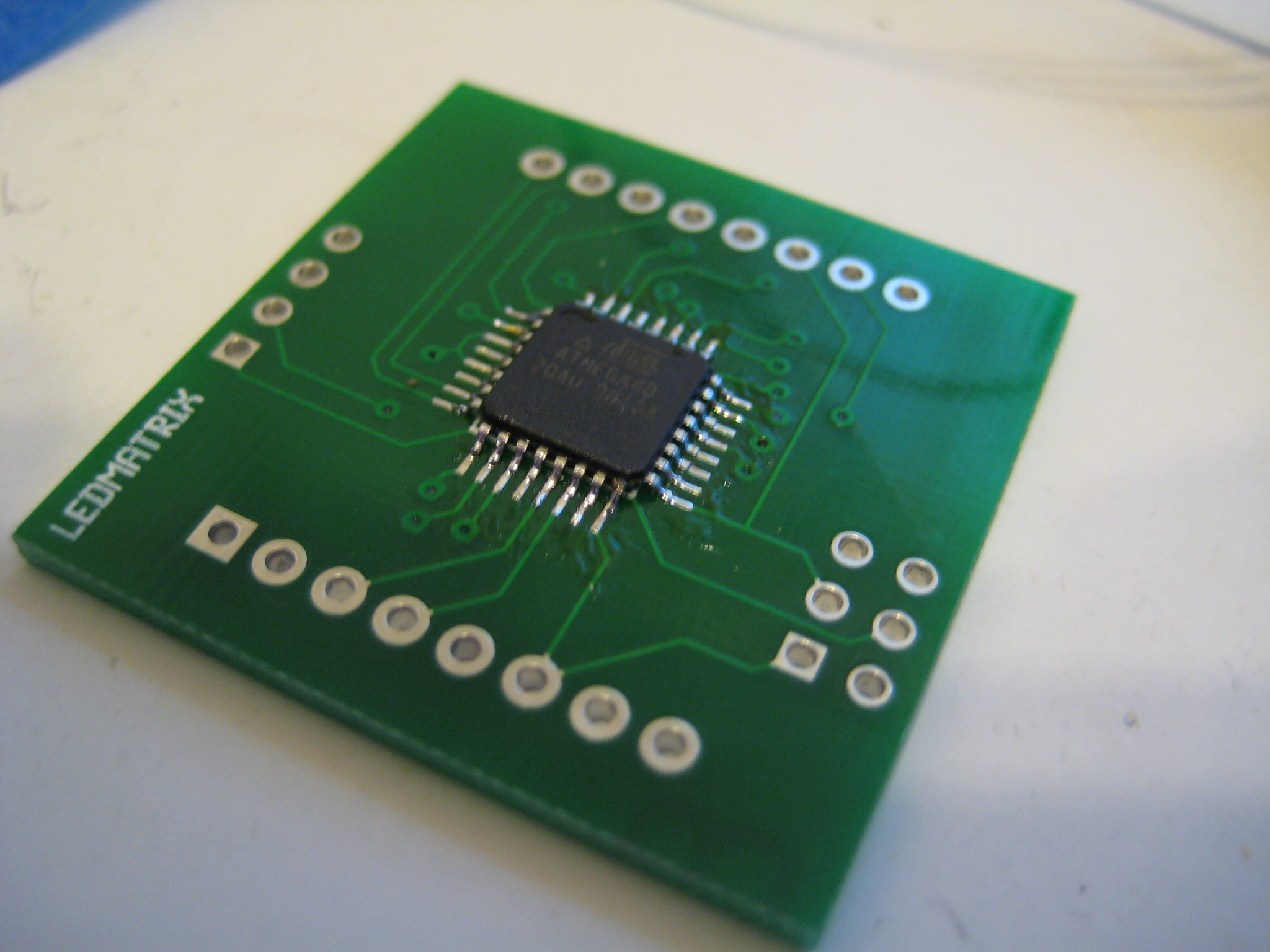
Have some more pretty pictures.


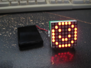
Yes, thats my USBtinyISP AVR Programmer in some of the photos. Being able to tap into USB power through it speeds up development - never need to unplug it. In the last photo I have the device plugged into an Iomega branded lithium ion cell from Allelectronics, just show that it can be done.
DISCLAIMER
All content is owned by its respective creators/licence holders.
Unless otherwise stated, everything else: Copyright © 2009-2010, Chlazza
 Initially I made plans around the Ningbo Flying Electronics Co., Ltd. (yes, that is apparently their real name) NFM-12881xx series of LED matrices. I figured that was what Futurlec would ship me, based on the part number in the picture on the details page for that part. I thought it odd that they didn't have an exact part number clearly listed on the info page, however - just a brief rundown of the electrical specs. When the box of parts arrived I was somewhat surprised to find they had shipped me Taiwan Oasis TOM-1088BMR-B displays instead. I dug up a datasheet and confirmed that the pinout was the same, but electrical specs were slightly different (the Oasis part had a recommended current of 12mA compared to 20mA for the Ningbo part). Not a big deal (this isn't going into space) but I'd still like to know what I'm buying before it arrives in my mailbox.
You may note number of 'switches' in the schematic on pins 23 through 26. These are intended as address pins - if a number of displays are connected on an I2C bus for example, these solder pads can be shorted to give each device a unique identifier. This lets the user dump the same code onto each device and allows for easy visual identification. These pads also serve are breakout points for these pins so the user can extend the functionality of the board (note that an alternate function of the pins is ADC input).
There is a standard six pin AVR programming header on board. I was careful to make sure the MOSI, MISO, and SCK lines were on pins that were intended to sink the display pins. That way we don't have these nets shorting to other pins on the '48 and preventing in-circuit programmers from accessing the chip successfully. I didn't think it would cause a problem - I don't think the other pins on microcontroller's pins are grounded when its being programed and I don't think the states matter - but I'd rather head off potential problems before they become an issue (particularly since the '48 is trapped under the permanently attached display). For all the headers I used a table surface and a screwdriver to push the plastic retaining thingy down the pins so the end of them was flush with the display side of the board.
Initially I made plans around the Ningbo Flying Electronics Co., Ltd. (yes, that is apparently their real name) NFM-12881xx series of LED matrices. I figured that was what Futurlec would ship me, based on the part number in the picture on the details page for that part. I thought it odd that they didn't have an exact part number clearly listed on the info page, however - just a brief rundown of the electrical specs. When the box of parts arrived I was somewhat surprised to find they had shipped me Taiwan Oasis TOM-1088BMR-B displays instead. I dug up a datasheet and confirmed that the pinout was the same, but electrical specs were slightly different (the Oasis part had a recommended current of 12mA compared to 20mA for the Ningbo part). Not a big deal (this isn't going into space) but I'd still like to know what I'm buying before it arrives in my mailbox.
You may note number of 'switches' in the schematic on pins 23 through 26. These are intended as address pins - if a number of displays are connected on an I2C bus for example, these solder pads can be shorted to give each device a unique identifier. This lets the user dump the same code onto each device and allows for easy visual identification. These pads also serve are breakout points for these pins so the user can extend the functionality of the board (note that an alternate function of the pins is ADC input).
There is a standard six pin AVR programming header on board. I was careful to make sure the MOSI, MISO, and SCK lines were on pins that were intended to sink the display pins. That way we don't have these nets shorting to other pins on the '48 and preventing in-circuit programmers from accessing the chip successfully. I didn't think it would cause a problem - I don't think the other pins on microcontroller's pins are grounded when its being programed and I don't think the states matter - but I'd rather head off potential problems before they become an issue (particularly since the '48 is trapped under the permanently attached display). For all the headers I used a table surface and a screwdriver to push the plastic retaining thingy down the pins so the end of them was flush with the display side of the board.